Nissan Rogue. Manual - part 772
HAC-110
< REMOVAL AND INSTALLATION >
[AUTOMATIC AIR CONDITIONING]
DOOR MOTOR
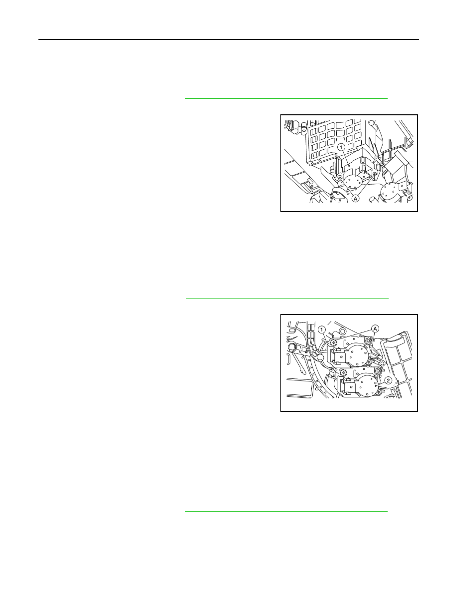
INTAKE DOOR MOTOR
INTAKE DOOR MOTOR : Removal and Installation
INFOID:0000000011276657
REMOVAL
1. Remove front foot duct (LH). Refer to
VTL-10, "FRONT FOOT DUCT : Removal and Installation"
2. Disconnect the harness connector from the intake door motor.
3. Remove screws (A) and intake door motor (1).
INSTALLATION
Installation is in the reverse order of removal.
MODE DOOR MOTOR
MODE DOOR MOTOR : Removal and Installation
INFOID:0000000011276658
REMOVAL
1. Remove front foot duct (RH). Refer to
VTL-10, "FRONT FOOT DUCT : Removal and Installation"
.
2. Disconnect the harness connector from the mode door motor.
3. Remove screws (A) and mode door motor (1).
(2): Air mix door motor (RH)
INSTALLATION
Installation is in the reverse order of removal.
AIR MIX DOOR MOTOR
AIR MIX DOOR MOTOR : Removal and Installation
INFOID:0000000011276659
REMOVAL
Air Mix Door Motor (LH)
1. Remove front foot duct (LH). Refer to
VTL-10, "FRONT FOOT DUCT : Removal and Installation"
2. Disconnect the harness connector from the air mix door motor (LH).
ALIIA0880ZZ
ALIIA0881ZZ