Nissan Rogue. Manual - part 775
HAC-122
< SYSTEM DESCRIPTION >
[MANUAL AIR CONDITIONING]
SYSTEM
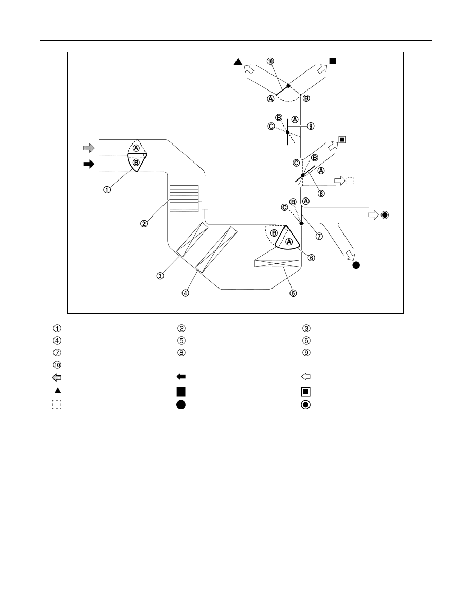
NOTE:
The sub defroster door and side ventilator door include a permanent opening and does not fully close.
Intake door
Blower motor
Air conditioner filter
Evaporator
Heater core
Air mix door
Foot door
Side ventilator door
Sub defroster door
Center ventilator and defroster door
Fresh air intake
Recirculation air
Discharge air
Defroster
Center ventilator
Side ventilator
Rear ventilator
Front foot
Rear foot
JMIIA3449ZZ