Nissan Rogue. Manual - part 695


  Index      Nissan     Nissan Rogue (2015 year) - Service and Repair Manual


Search            


Content   ..  693  694  695  696   ..


Nissan Rogue. Manual - part 695


FRONT DRIVE SHAFT

FAX-73

< UNIT DISASSEMBLY AND ASSEMBLY >

[AWD]

C

E

F

G

H

I

J

K

L

M

A

B

FAX

N

O

P

Transaxle Side

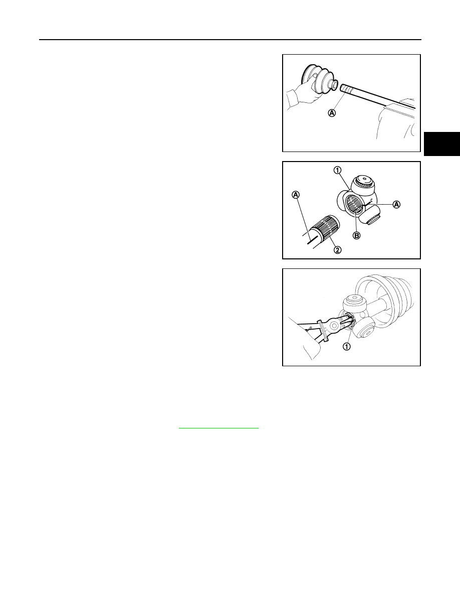
1. Install new boot and new small boot band on shaft.

CAUTION:

• Do not reuse boot and boot bands. 

• Cover drive shaft serration with protective tape (A) to pre-

vent damage to boot during installation.

2. Remove the tape wrapped around the serration on shaft.

3. Align the matching mark (A) on the spider assembly (1) with the

matching mark on the shaft (2). Install the spider assembly to

the shaft with the chamfer (B) facing the shaft.

4. Secure spider assembly onto shaft with snap ring (1).

CAUTION:

Do not reuse snap ring.

5. Apply the appropriate amount of Genuine NISSAN Grease to spider assembly and sliding surface.

NOTE:

Always check with the Parts Department for the latest parts information.

6. Assemble the housing onto spider assembly, and apply the specified amount of grease.

NOTE:

Always check with the Parts Department for the latest parts information.

7. Align matching marks put during the removal of housing.
8. Install stopper ring.

CAUTION:

Do not reuse stopper ring.

JPDIF0009ZZ

JPDIF0017ZZ

JPDIF0014ZZ

Grease quantity

: Refer to 

FAX-77, "Drive Shaft"

.

FAX-74

< UNIT DISASSEMBLY AND ASSEMBLY >

[AWD]

FRONT DRIVE SHAFT

9. Install boot securely into grooves (indicated by “*” marks)

shown.

CAUTION:

If grease adheres to the boot mounting surface (indicated

“*” mark) on shaft or housing, boot may be removed.

Remove all grease from the boot mounting surface.

10. To prevent the deformation of the boot, adjust the boot installa-

tion length (L) to the value shown below by inserting the suitable

tool into the inside of boot from the large diameter side of boot

and discharging inside air.

CAUTION:

• If the boot installation length is outside the standard, it may cause breakage of boot.

• Be careful not to touch the inside of the boot with the tip of tool.

11. Install new boot bands securely as shown.

CAUTION:

Do not reuse boot band.

12. Secure housing and shaft, and then make sure that they are in the correct position when rotating boot.

Reinstall them with new boot bands when the mounting positions become incorrect.

CAUTION:

Do not reuse boot bands.

13. Install dust shield to housing.

CAUTION:

Do not reuse dust shield.

14. Install circular clip to housing.

CAUTION:

Do not reuse circular clip.

Support Bearing

1. Install dust shield on housing.

CAUTION:

Do not reuse dust shield.

2. Press support bearing (1) onto housing to using the suitable tool

(A).

3. Install snap ring.

CAUTION:

Do not reuse snap ring.

Boots installed 
length (L)

: Refer to 

FAX-77, "Drive Shaft"

.

JPDIF0238ZZ

PDIA1188J

JPDIF0056ZZ

FRONT DRIVE SHAFT

FAX-75

< UNIT DISASSEMBLY AND ASSEMBLY >

[AWD]

C

E

F

G

H

I

J

K

L

M

A

B

FAX

N

O

P

4. Install dust shields.

CAUTION:

Do not reuse dust shields.

Wheel Side

1. Insert the amount of Genuine NISSAN Grease into joint sub-

assembly (1) serration hole until grease begins to ooze from ball

groove and serration hole.

CAUTION:

After inserting the grease, use a paper shop cloth to wipe

off old grease that has oozed out.

NOTE:

Always check with the Parts Department for the latest parts

information. 

2. Install new boot and new small boot band on shaft.

CAUTION:

• Do not reuse the boot and boot bands.

• Cover drive shaft serration with protective tape (A) to pre-

vent damage to boot during installation.

3. Remove protective tape wound around serrated part of shaft.

4. Attach new circlip to shaft. The circlip must fit securely into shaft

groove. Attach nut to joint sub-assembly.

Use a suitable tool to press-fit.

CAUTION:

Do not reuse circlip.

5. Insert the amount of new Genuine NISSAN Grease listed below into housing from large end of boot.

NOTE:

Always check with the Parts Department for the latest parts information. 

JPDIF0127ZZ

JPDIF0008ZZ

JPDIF0009ZZ

RAC0049D

Grease quantity

: Refer to 

FAX-77, "Drive Shaft"

.

FAX-76

< UNIT DISASSEMBLY AND ASSEMBLY >

[AWD]

FRONT DRIVE SHAFT

6. Install boot securely into grooves (indicated by "* marks) as

shown.

CAUTION:

If there is grease on boot mounting surfaces (indicated by

"* marks) on shaft or joint sub-assembly, boot may come

off. Remove all grease from surfaces.

7. Make sure boot installation length (L) is the specified length.

Insert a suitable tool into the large end of boot. Bleed air from

boot to prevent boot deformation. 

CAUTION:

• Boot may break if boot installation length is less than standard value.

• Be careful that suitable tool does not contact inside surface of boot.

8. Install new large and small boot bands securely using Tool.

CAUTION:

Do not reuse boot bands.

9. Secure boot band so that dimension (M) meets specification as

shown. 

10. Attempt to rotate the boot to check whether or not the boot bands are securing the boot. If the boot is not

secure, remove the boot bands, reposition the boot, and install new boot bands.

CAUTION:

Do not reuse boot bands.

Boot installation 
length (L)

: Refer to 

FAX-77, "Drive Shaft"

.

Tool number

: KV40107300 (

JPDIF0144ZZ

RAC1133D

Dimension (M)

: Refer to 

FAX-77, "Drive 

Shaft"

.

DSF0047D


Content   ..  693  694  695  696   ..