Nissan Rogue. Manual - part 693
FRONT DRIVE SHAFT
FAX-65
< UNIT DISASSEMBLY AND ASSEMBLY >
[AWD]
C
E
F
G
H
I
J
K
L
M
A
B
FAX
N
O
P
UNIT DISASSEMBLY AND ASSEMBLY
FRONT DRIVE SHAFT
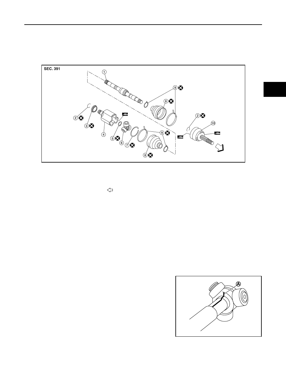
Exploded View (LH)
INFOID:0000000011278659
Disassembly and Assembly (LH)
INFOID:0000000011278660
DISASSEMBLY
Transaxle Side
1. Secure front drive shaft in a vise.
CAUTION:
When securing shaft in a vise, always use copper or aluminum plates between the vise and shaft.
2. Remove boot bands and slide the boot back.
3. Remove stopper ring.
4. Put matching marks on housing and shaft, and then pull out housing from shaft.
CAUTION:
Use paint or an equivalent for matching marks. Do not scratch the surfaces.
5. Put matching marks (A) on the spider assembly and shaft.
CAUTION:
Use paint or an equivalent for matching marks. Do not
scratch the surfaces.
1.
Shaft
2.
Circular clip
3.
Dust shield
4.
Housing
5.
Snap ring
6.
Spider assembly
7.
Stopper ring
8.
Boot
9.
Boot band
10. Joint sub-assembly
Wheel side
AWDIA1161ZZ
JPDIF0006ZZ