Nissan Rogue. Manual - part 691
FRONT DRIVE SHAFT
FAX-57
< REMOVAL AND INSTALLATION >
[AWD]
C
E
F
G
H
I
J
K
L
M
A
B
FAX
N
O
P
FRONT DRIVE SHAFT
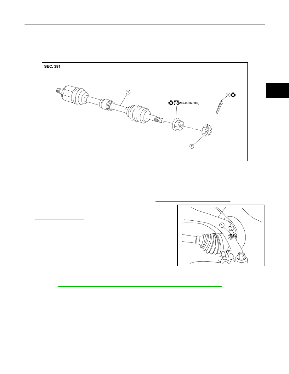
Exploded View (LH)
INFOID:0000000011278654
Removal and Installation (LH)
INFOID:0000000011278655
REMOVAL
1. Remove front wheel and tire using power tool. Refer to
WT-67, "Removal and Installation"
2. Remove the bolt (1) and separate the front wheel sensor from
the steering knuckle. Refer to
.
CAUTION:
• Failure to separate the front wheel sensor from the steer-
ing knuckle may result in damage to the front wheel sen-
sor.
• Pull out the front wheel sensor, being careful to turn it as
little as possible. Do not pull on wheel sensor harness.
3. Remove brake caliper torque member bolts, leaving brake hose attached. Position the brake caliper aside
BR-37, "BRAKE CALIPER ASSEMBLY (1 PISTON TYPE) : Exploded View"
(1 PISTON
TYPE), or
BR-42, "BRAKE CALIPER ASSEMBLY (2 PISTON TYPE) : Exploded View"
(2 PISTON TYPE).
CAUTION:
Do not depress brake pedal while brake caliper is removed.
1.
Drive shaft
2.
Nut retainer
3.
Cotter pin
AWDIA1204ZZ
ALDIA0526ZZ