Nissan Rogue. Manual - part 692
FRONT DRIVE SHAFT
FAX-61
< REMOVAL AND INSTALLATION >
[AWD]
C
E
F
G
H
I
J
K
L
M
A
B
FAX
N
O
P
Removal and Installation (RH)
INFOID:0000000011278657
REMOVAL
1. Remove front wheel and tire using power tool. Refer to
WT-67, "Removal and Installation"
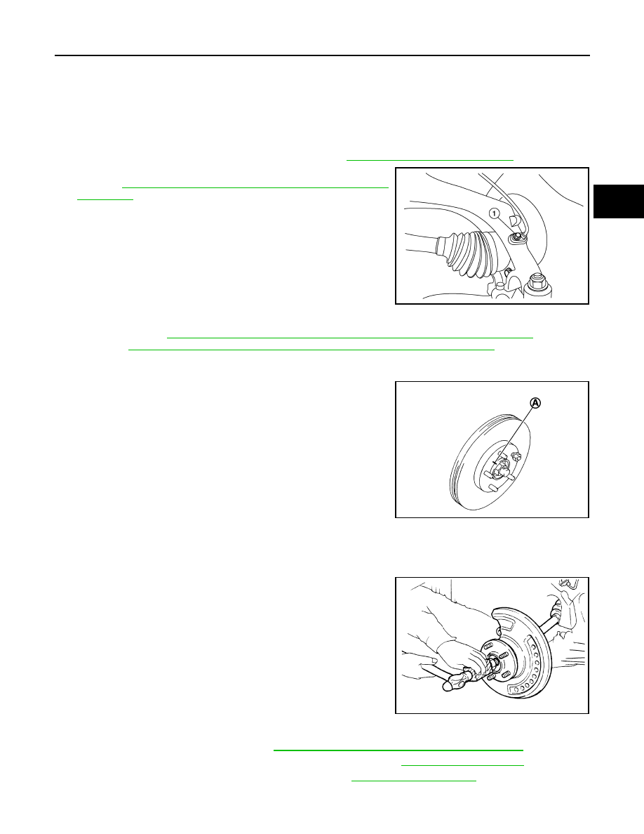
2. Remove wheel sensor bolt (A) and position wheel sensor aside.
Refer to
BRC-130, "FRONT WHEEL SENSOR : Removal and
.
CAUTION:
• Failure to separate the front wheel sensor from the steer-
ing knuckle may result in damage to the front wheel sen-
sor.
• Pull out the front wheel sensor, being careful to turn it as
little as possible. Do not pull on wheel sensor harness.
3. Remove brake caliper torque member bolts, leaving brake hose attached. Position the brake caliper aside
BR-37, "BRAKE CALIPER ASSEMBLY (1 PISTON TYPE) : Exploded View"
(1 PISTON
TYPE), or
BR-42, "BRAKE CALIPER ASSEMBLY (2 PISTON TYPE) : Exploded View"
(2 PISTON TYPE).
CAUTION:
Do not depress brake pedal while brake caliper is removed.
4. Put alignment marks (A) on disc brake rotor and wheel hub and
bearing. Remove disc brake rotor.
CAUTION:
Do not drop the disc brake rotor.
5. Remove cotter pin.
6. Remove the nut retainer.
7. Loosen the wheel hub lock nut from the drive shaft using power tool.
8. Using a piece of wood and a suitable tool, tap on the lock nut to
disengage the drive shaft from the wheel hub and bearing.
CAUTION:
• Do not place the drive shaft joint at an extreme angle. Be
careful not to over extend the slide joint.
• Do not allow the drive shaft to hang without support.
NOTE:
Use a suitable puller if drive shaft cannot be separated from the
wheel hub and bearing.
9. Remove the wheel hub lock nut.
10. Remove the engine side cover. Refer to
EXT-28, "FENDER PROTECTOR : Exploded View"
.
11. Remove the lower nut and bolt from the steering knuckle. Refer to
.
12. Separate transverse link from steering knuckle. Refer to
.
13. Separate drive shaft from wheel hub and bearing and reposition drive shaft aside with wire.
1.
Support bearing bracket
2.
Drive shaft
3.
Nut retainer
4.
Cotter pin
5.
Bearing retainer
A.
Refer to installation.
ALDIA0526ZZ
JPDIG0066ZZ
JPDIG0070ZZ