Nissan Rogue. Manual - part 622


  Index      Nissan     Nissan Rogue (2015 year) - Service and Repair Manual


Search            


Content   ..  620  621  622  623   ..


Nissan Rogue. Manual - part 622


FRONT FOG LAMP AIMING ADJUSTMENT

EXL-117

< PERIODIC MAINTENANCE >

[HALOGEN HEADLAMP]

C

D

E

F

G

H

I

J

K

M

A

B

EXL

N

O

P

FRONT FOG LAMP AIMING ADJUSTMENT

Aiming Adjustment Procedure

INFOID:0000000011280780
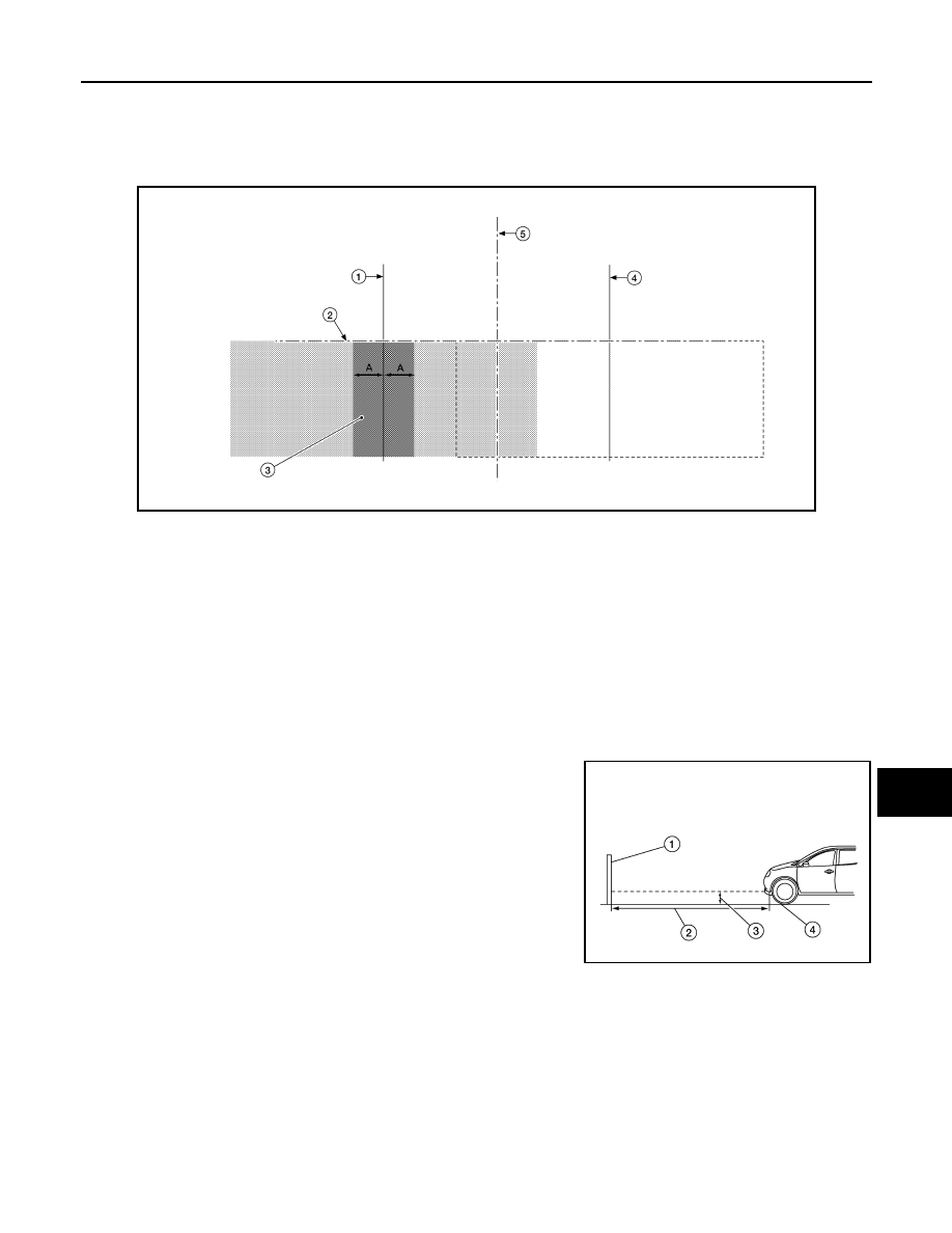
Aiming Chart

NOTE:

• (LH) Front fog lamp aiming specifications shown, (RH) similar.

• Check the following conditions before performing the aiming adjustment.

- Keep all tires inflated to correct pressure.

- Place vehicle on level ground.

- See that vehicle is unloaded (except for full levels of coolant, engine oil and fuel, and spare tire, jack, and

tools). Have the driver or equivalent weight placed in driver seat.

- When performing adjustment, if necessary, cover the headlamps and opposite front fog lamp.
1. Set the distance between the screen and the center of the front

fog lamp lens as shown.

(1) Aiming screen or a matte white surface

(2) 7.62 m (25 ft)

(3) Floor to center of front fog lamp lens

(4) Floor

2. Turn front fog lamps ON.

AWLIA2219ZZ

1.

Vertical center line of front fog 
lamp (LH)

2.

Lamp center above ground

3.

Front fog lamp high intensity 
area (LH)

4.

Vertical center line of front fog 
lamp (RH)

5.

Vertical center axis

A.

100mm (4in)

AWLIA2318ZZ

EXL-118

< PERIODIC MAINTENANCE >

[HALOGEN HEADLAMP]

FRONT FOG LAMP AIMING ADJUSTMENT

3. Access adjusting screw (A) from underneath front bumper fas-

cia. Adjust front fog lamps using adjusting screw so that the top

edge of the high intensity zone is at the front fog lamp centers

above ground.

ALLIA0035ZZ

FRONT COMBINATION LAMP

EXL-119

< REMOVAL AND INSTALLATION >

[HALOGEN HEADLAMP]

C

D

E

F

G

H

I

J

K

M

A

B

EXL

N

O

P

REMOVAL AND INSTALLATION

FRONT COMBINATION LAMP

Exploded View

INFOID:0000000011280781

Removal and Installation

INFOID:0000000011280782

REMOVAL

1. Remove front bumper fascia. Refer to 

EXT-17, "Removal and Installation"

.

2. Remove front combination lamp bolts and clip.
3. Pull front combination lamp forward. 
4. Disconnect the harness connectors from the front combination lamp and remove. 

INSTALLATION

Installation is in the reverse order of removal.

NOTE:

After installation, perform headlamp aiming adjustment. Refer to 

EXL-114, "Inspection"

.

Bulb Replacement

INFOID:0000000011280783

WARNING:

Do not touch bulb by hand while it is lit or right after being turned off. Burning may result.

CAUTION:

• Do not touch the glass surface of the bulb with bare hands or allow oil or grease to get on it to pre-

vent damage to the bulb.

1.

Front fender

2.

Front combination lamp

Clip

ALLIA1401ZZ

EXL-120

< REMOVAL AND INSTALLATION >

[HALOGEN HEADLAMP]

FRONT COMBINATION LAMP

• Do not leave bulb out of lamp reflector for a long time because dust, moisture smoke, etc. may affect

the performance of lamp. When replacing bulb, be sure to replace it with new one.

HEADLAMP (LOW BEAM) BULB

Removal

1. Rotate the bulb counterclockwise and remove from the front combination lamp.
2. Disconnect the harness connector from bulb and remove.

Installation

Installation is in the reverse order of removal.

CAUTION:

After installing the bulb, install the bulb socket securely for watertightness.

HEADLAMP (HIGH BEAM) BULB

Removal

1. Remove plastic cover.
2. Rotate the bulb counterclockwise and remove from the front combination lamp.
3. Disconnect the harness connector from bulb and remove.

Installation

Installation is in the reverse order of removal.

CAUTION:

After installing the bulb, install the bulb socket securely for watertightness.

SIDE MARKER LAMP BULB

Removal

1. Rotate the bulb counterclockwise and remove from the front combination lamp.
2. Remove the bulb from the bulb socket.

Installation

Installation is in the reverse order of removal.

CAUTION:

After installing the bulb, install the bulb socket securely for watertightness.

TURN SIGNAL LAMP BULB

Removal

1. Rotate bulb socket counterclockwise and remove from the front combination lamp.
2. Remove the bulb from bulb socket.

Installation

Installation is in the reverse order of removal.

CAUTION:

After installing the bulb, install the bulb socket securely for watertightness.


Content   ..  620  621  622  623   ..