Nissan Rogue. Manual - part 623
FRONT FOG LAMP
EXL-121
< REMOVAL AND INSTALLATION >
[HALOGEN HEADLAMP]
C
D
E
F
G
H
I
J
K
M
A
B
EXL
N
O
P
FRONT FOG LAMP
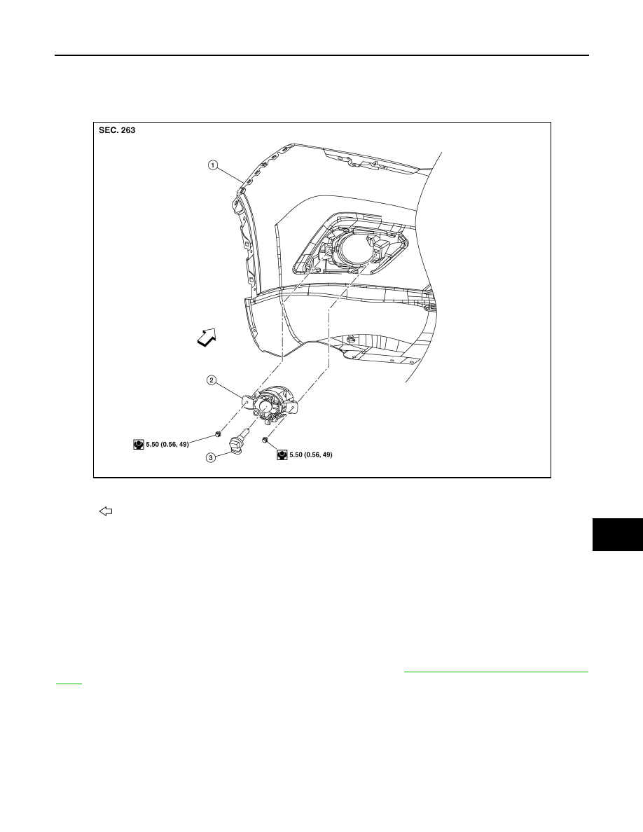
Exploded View
INFOID:0000000011280784
Removal and Installation
INFOID:0000000011280785
REMOVAL
1. Partially remove front fender protector.
2. Disconnect the harness connector from the front fog lamp.
3. Remove front fog lamp bolts and front fog lamp.
INSTALLATION
Installation in the reverse order of removal.
NOTE:
After installation, perform front fog lamp aiming adjustment. Refer to
EXL-117, "Aiming Adjustment Proce-
.
Bulb Replacement
INFOID:0000000011280786
WARNING:
Do not touch bulb by hand while it is lit or right after being turned off. Burning may result.
CAUTION:
• Do not touch the glass surface of the bulb with bare hands or allow oil or grease to get on it to pre-
vent damage to the bulb.
1.
Front bumper fascia
2.
Front fog lamp
3.
Front fog lamp bulb
Front
AWLIA2317ZZ