Nissan Rogue. Manual - part 575


  Index      Nissan     Nissan Rogue (2015 year) - Service and Repair Manual


Search            


Content   ..  573  574  575  576   ..


Nissan Rogue. Manual - part 575


CYLINDER HEAD

EM-65

< REMOVAL AND INSTALLATION >

C

D

E

F

G

H

I

J

K

L

M

A

EM

N

P

O

d. Finish valve seat to the specified dimension using suitable tool.

Refer to 

EM-122, "Cylinder Head"

.

CAUTION:

When using valve seat cutter, firmly grip the cutter handle

with both hands. Then, press on the contacting surface all

around the circumference to cut in a single drive. Improper

pressure on the cutter or cutting many different times may

result in stage valve seat.

e. Using compound, grind to adjust valve.

f.

Check again for normal contact. Refer to 

EM-122,

"Cylinder Head"

.

3. Apply new engine oil to new valve oil seal joint surface and seal lip.
4. Install new valve oil seal using suitable tool (A) as shown.

NOTE:

Dimension is height measured before installing valve spring

(with valve spring seat).

5. Install valve.

• Install larger diameter to intake side.

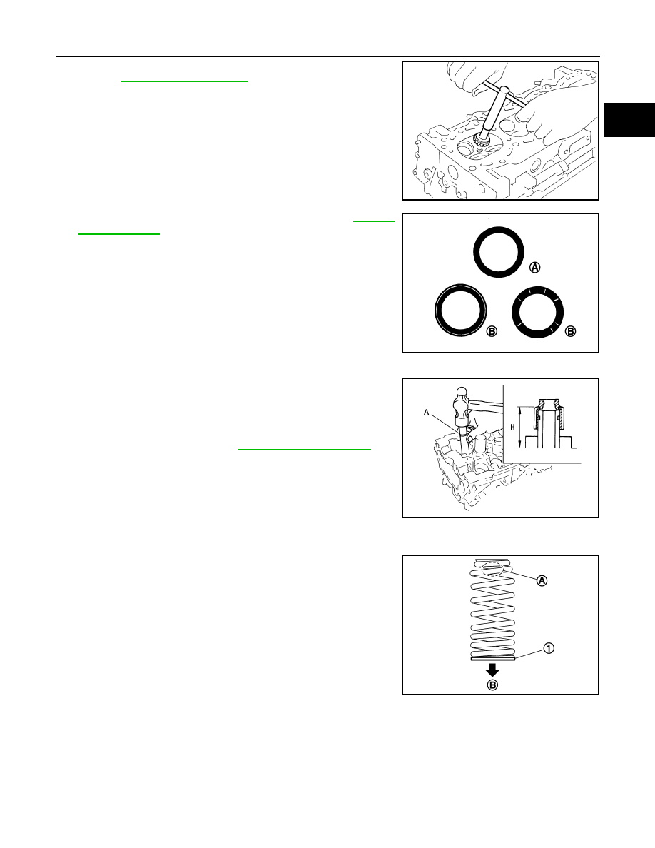
6. Install valve spring with valve spring seat (1).

• Install valve spring so that the identification color faces upward

(A).

• Install smaller pitch to cylinder head side (B).

• Confirm the identification color of the valve spring.

7. Install valve spring retainer.
8. Install valve collet.

SEM934C

(A)

: OK

(B)

: NG

JPBIA0187ZZ

Projection (H)

: Refer to 

EM-122, "Cylinder Head"

ALBIA0864GB

Intake

: White

Exhaust

: Light blue

JPBIA4479ZZ

EM-66

< REMOVAL AND INSTALLATION >

CYLINDER HEAD

• Compress valve spring using suitable tool (A). Install valve col-

let with a magnet hand.

CAUTION:

When working do not damage valve lifter holes.

• Tap valve stem edge lightly with a plastic hammer after instal-

lation to check its installed condition.

9. Install valve lifter.
10. Install spark plug. Refer to 

EM-19, "Removal and Installation"

Inspection After Disassembly

INFOID:0000000011279965

CYLINDER HEAD DISTORTION

1. Wipe off engine oil and remove water scale deposits, old gasket,

old sealer, and carbon using a suitable tool.

CAUTION:

Use care not to allow gasket debris to enter passages for

engine oil or engine coolant.

2. At each of several locations on bottom surface of cylinder head,

measure distortion in six directions using suitable tools (A, B).

• If measurements exceed the limit, replace cylinder head.

VALVE DIMENSIONS

1. Check dimensions of each valve. Refer to 

EM-122, "Cylinder Head"

.

2. If dimensions are out of the standard, replace valve and check valve seat contact.

VALVE SEAT CONTACT

NOTE:

After confirming that the dimensions of valve guides and valves are within specifications, perform this proce-

dure:
1. Apply prussian blue (or white lead) onto contacting surface of

valve seat to check the condition of the vavle contact on the seat

surface.

2. Ensure that the contact area band is continuous all around the

circumference.

3. If the contact area is not continuous, grind to adjust valve fitting and check again. If the contacting surface

still has NG conditions even after the re-check, replace the valve seat.

VALVE GUIDE CLEARANCE

AWBIA1760ZZ

Limit

: Refer to 

EM-122, "Cylinder Head"

PBIC3207J

(A)

: OK

(B)

: NG

JPBIA0187ZZ

CYLINDER HEAD

EM-67

< REMOVAL AND INSTALLATION >

C

D

E

F

G

H

I

J

K

L

M

A

EM

N

P

O

1. Measure diameter of valve stem using suitable tool (A) as

shown.

2. Measure inner diameter of valve guide using suitable tool.

3. Valve guide clearance = (Valve guide inner diameter) - (Valve

stem diameter)

4. If the calculated value exceeds the limit, replace valve and/or valve guide. When valve guide must be

replaced. Refer to 

EM-61, "Disassembly and Assembly"

VALVE SPRING SQUARENESS

CAUTION:

Do not remove the valve spring seat from the valve spring
1. Set a try square (A) along the side of valve spring and rotate

spring. Measure the maximum clearance between the top of

spring and try square.

2. If the valve spring exceeds the limit, replace the valve spring

with the valve spring seat.

VALVE SPRING PRESSURE LOAD

CAUTION:

Do not remove the valve spring seat.
1. Check valve spring pressure with valve spring seat installed at

the specified spring height.

2. If the installation load or load with valve open is out of the stan-

dard, replace valve spring with valve spring seat.

INSPECTION AFTER INSTALLATION

Inspection for Leaks
1. Before starting engine, check oil/fluid levels including engine coolant and engine oil. If less than required

quantity, fill to the specified level. Refer to 

LU-8, "Refilling"

.

2. Use the following steps to check for fuel leaks.
a. Turn ignition switch "ON" (with engine stopped).
b. With fuel pressure applied to fuel piping, check for fuel leaks at connection points.

Standard

: Refer to 

EM-122, "Cylinder Head"

Standard

: Refer to 

EM-122, "Cylinder Head"

Standard and Limit

: Refer to 

EM-122, "Cylinder Head"

AWBIA0068ZZ

(B) : Contact

Limit

: Refer to 

EM-122, "Cylinder Head"

.

PBIC3219J

Standard

: Refer to 

EM-122, "Cylinder Head"

.

SEM113

EM-68

< REMOVAL AND INSTALLATION >

CYLINDER HEAD

c.

Start engine.

d. With engine speed increased, check again for fuel leaks at connection points.
3. Run engine to check for unusual noise and vibration.

NOTE:

If hydraulic pressure inside timing chain tensioner drops after removal and installation, slack in the guide

may generate a pounding noise during and just after engine start. However, this is normal. Noise will stop

after hydraulic pressure rises.

4. Warm up engine thoroughly to check there are no fuel leaks, exhaust gas leaks, or any oil/fluid leaks

including engine oil and engine coolant.

5. Bleed air from lines and hoses of applicable lines, such as in cooling system.
6. After cooling down engine, again check oil/fluid levels including engine oil and engine coolant. Refill to the

specified level, if necessary.

Summary of the inspection items:

*: Power steering fluid, brake fluid, etc.

Items

Before starting engine

Engine running

After engine stopped

Engine coolant

Level

Leakage

Level

Engine oil

Level

Leakage

Level

Transmission / 
transaxle fluid

AT & CVT Models

Leakage

Level / Leakage

Leakage

MT Models

Level / Leakage

Leakage

Level / Leakage

Other oils and fluids*

Level

Leakage

Level

Fuel

Leakage

Leakage

Leakage

Exhaust gases

Leakage


Content   ..  573  574  575  576   ..