Nissan Rogue. Manual - part 574


  Index      Nissan     Nissan Rogue (2015 year) - Service and Repair Manual


Search            


Content   ..  572  573  574  575   ..


Nissan Rogue. Manual - part 574


CYLINDER HEAD

EM-61

< REMOVAL AND INSTALLATION >

C

D

E

F

G

H

I

J

K

L

M

A

EM

N

P

O

Disassembly and Assembly

INFOID:0000000011279964

CAUTION:

• When installing camshafts, chain tensioners, oil seals or other sliding parts, lubricate contacting

surfaces with new engine oil.

• Apply new engine oil to threads and seat surfaces when installing the cylinder head, camshaft

sprocket, crankshaft pulley and camshaft bracket.

• Attach tags to valve lifters so all parts are assembled in their original position.

CAUTION:

Read PRECAUTION carefully.

The exhaust valve contains metallic sodium. Therefore, extreme caution must be taken when handling

and disposing of the exhaust valve. Refer to 

EM-4, "Special Cautions to Ensure the Safe Disposal of
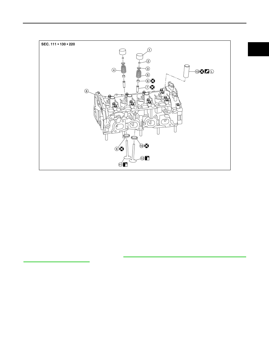
Sodium-filled Exhaust Valves"

DISASSEMBLY

1. Remove the valve lifter.

NOTE:

Confirm installation point to return valve lifter to original location during assembly.

1.

Valve lifter

2.

Valve collet

3.

Valve spring retainer 

4.

Valve spring (INT)

5.

Valve spring (EXH)

6.

Valve oil seal

7.

Valve guide

8.

Cylinder head

9.

Valve seat (INT)

10. Valve seat (EXH)

11. Valve (INT)

12. Valve (EXH)

13. Spark plug tube

L

Apply thread locking sealant

AWBIA1924ZZ

EM-62

< REMOVAL AND INSTALLATION >

CYLINDER HEAD

2. Remove valve collet, valve spring retainer, and valve spring

using suitable tool (A).  Remove valve collet with magnetic hand. 

CAUTION:

• Be careful not to damage valve lifter holes.

• Install suitable tool (A) in the center of valve spring

retainer (1) to install it.

3. Remove valve spring retainer and valve spring (with valve spring seat).

CAUTION:

Do not remove valve spring seat from valve spring.

4. Push valve stem to combustion chamber side, and remove valve. 

• Inspect valve guide clearance before removal. Refer to 

EM-66, "Inspection After Disassembly"

.

• Confirm installation point to return valve to original location during assembly.

5. Remove valve oil seal using suitable tool (A).

6. Remove valve seat, if necessary.

• Bore out old seat until it collapses. Boring should not continue beyond the bottom face of the seat

recess in cylinder head. Set the machine depth stop to ensure this. Refer to 

EM-122, "Cylinder Head"

.

CAUTION:

Do not bore excessively to prevent damage to cylinder head.

7. Remove valve guide, if necessary.

AWBIA1760ZZ

JPBIA4477ZZ

ALBIA0863GB

CYLINDER HEAD

EM-63

< REMOVAL AND INSTALLATION >

C

D

E

F

G

H

I

J

K

L

M

A

EM

N

P

O

a. To remove valve guide, heat cylinder head to 110

°C to 130°C

(230

°F to 266°F) by soaking in heated engine oil (A).

WARNING:

Cylinder head contains heat. When working, wear protec-

tive equipment to avoid getting burned.

b. Drive out valve guide using suitable tool.

8. Remove spark plugs. Refer to 

EM-19, "Removal and Installation"

9. Remove spark plug tubes, if necessary, using suitable tool.

CAUTION:

• Be careful not to damage cylinder head.

• Do not remove spark plug tube if not necessary. Once removed, the spark plug tube cannot be

reused because of deformation during removal.

ASSEMBLY

1. Install valve guide, if removed.
a. Ream cylinder head valve guide hole using suitable tool (A).

Refer to 

EM-122, "Cylinder Head"

.

b. Heat cylinder head to 110

°C to 130°C (230°F to 266°F) by soak-

ing in heated engine oil (A).

WARNING:

Cylinder head contains heat. When working, wear protec-

tive equipment to avoid getting burned.

PBIC3214J

SEM931C

AWBIA1449ZZ

PBIC3214J

EM-64

< REMOVAL AND INSTALLATION >

CYLINDER HEAD

c.

Press valve guide (1) into cylinder head (2) from camshaft side

to dimension as shown.

d. Apply reamer finish to valve guide using suitable tool (A).

2. Install valve seat, if removed.
a. Ream cylinder head (1) recess diameter for service valve seat

(2).

b. Heat cylinder head to 110

°C to 130°C (230°F to 266°F) by soak-

ing in heated engine oil (A).

WARNING:

Cylinder head contains heat. When working, wear protec-

tive equipment to avoid getting burned.

c.

Allow valve seats to cool with dry ice. Press-fit valve seat into cylinder head.

CAUTION:

Do not touch cold valve seats directly.

Projection (H)

: Refer to 

EM-122, "Cylinder Head"

PBIC3217J

Standard

: Refer to 

EM-122, "Cylinder Head"

AWBIA1449ZZ

PBIC3218J

PBIC3214J


Content   ..  572  573  574  575   ..