Nissan Rogue. Manual - part 572


  Index      Nissan     Nissan Rogue (2015 year) - Service and Repair Manual


Search            


Content   ..  570  571  572  573   ..


Nissan Rogue. Manual - part 572


TIMING CHAIN

EM-53

< REMOVAL AND INSTALLATION >

C

D

E

F

G

H

I

J

K

L

M

A

EM

N

P

O

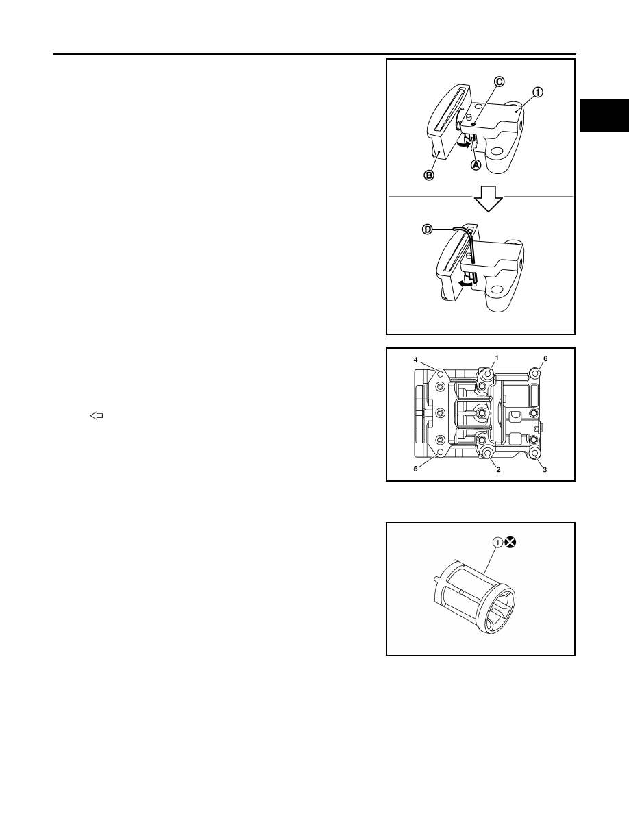
18. Press stopper tab (A) in the direction shown to push the timing

chain slack guide (B) toward timing chain tensioner (1) for the

balancer unit.

• The timing chain slack guide (B) is released by pressing the

stopper tab (A). As a result, the timing chain slack guide (B)

can be moved.

19. Insert stopper pin (D) into tensioner body hole (C) to secure tim-

ing chain slack guide (B).

NOTE:

Use a hard metal pin with a diameter of approximately 1.2 mm

(0.047 in) as a stopper pin. 

20. Remove timing chain tensioner (1) for balancer unit.
21. Secure width across flats of the balancer unit LH side shaft

using a suitable tool. Loosen the balancer unit sprocket bolt.

22. Remove balancer unit timing chain, balancer unit sprocket and

crankshaft sprocket.

23. Loosen bolts in the reverse order shown, and remove balancer

unit.

CAUTION:

• Do not disassemble balancer unit.

INSPECTION AFTER REMOVAL

Oil Filter

• Check that there is no foreign material on the oil filter (1) and check

for clogging.

• Check the oil filter for damage.

• If there is damage, replace the oil filter.

CAUTION:

Do not reuse oil filter.

Timing Chain

PBIC5314E

: Engine front

AWBIA2003ZZ

AWBIA2322ZZ

EM-54

< REMOVAL AND INSTALLATION >

TIMING CHAIN

Check the timing chain for cracks (A) or excessive wear (B). If a

defect is found, replace the timing chain.

Balancer Unit Bolt Outer Diameter

• Measure outer diameters (d1, d2) at the two positions as shown.

• Measure d2 within the range (A).

• If the value difference (d1 - d2) exceeds the limit, replace the bal-

ancer unit bolt with a new one.

INSTALLATION

1. Make sure the crankshaft key points straight up.
2. Install the balancer unit and tighten the bolts in the numerical

order as shown:

CAUTION:

• When reusing a bolt, check its outer diameter before

installation. Follow the Balancer Unit Bolt Outer Diameter

procedure.

• Apply new engine oil to threads and seating surfaces of

bolts.

• Check tightening angle with an angle wrench (A) or a pro-

tractor. Do not make judgment by visual check alone.

AWBIA2004ZZ

Limit 

: 0.15 mm (0. 0059 in) or more

KBIA0126E


: Engine front

AWBIA2003ZZ

Tool number 

: KV10112100 (BT-8653-A)

Step 1

Bolts 1-5

: 42 N·m (4.3 kg-m, 31 ft-lb)

Bolt 6

: 36 N·m (3.7 kg-m, 27 ft-lb)

Step 2

Bolts 1-5

: 120

° + 5°

Bolt 6

: 90

° + 5°

Step 3

Loosen in reverse 
order 

: 0 N·m (0 kg-m, 0 ft-lb)

Step 4

Bolts 1-5

: 42 N·m (4.3 kg-m, 31 ft-lb)

Bolt 6

: 36 N·m (3.7 kg-m, 27 ft-lb)

Step 5

Bolts 1-5

: 120

° + 5°

Bolt 6

: 90

° + 5°

ALBIA0201ZZ

TIMING CHAIN

EM-55

< REMOVAL AND INSTALLATION >

C

D

E

F

G

H

I

J

K

L

M

A

EM

N

P

O

3. Install the crankshaft sprocket (1) and timing chain (2) for the

balancer unit.

• Make sure that the crankshaft sprocket (1) is positioned with

mating marks (A) on the block and sprocket meeting at the

top.

• Install it by lining up mating marks on each sprocket (A), (C)

and timing chain (B), (D). 

• (B): Pink link

• (D): Yellow link

4. Install timing chain tensioner for balancer unit (1).

• Compress the plunger, insert a stopper pin (A), and then install

the tensioner for the balancer unit. 

• Do not pull out (

) the stopper pin until after installing the tim-

ing chain tensioner for balancer unit.

• Check matching mark position of balancer unit drive chain and

each sprocket again.

5. Install camshaft sprockets.

• Install them by lining up the mating marks on each camshaft

sprocket (B) with the ones painted on the timing chain (A) dur-

ing removal.

• Before installation of chain tensioner, it is possible to re-match

the marks on timing chain with the ones on each sprocket.   

CAUTION:

• Aligned mating marks could slip. Therefore, after match-

ing them, hold the timing chain in place by hand.

• Before and after installing chain tensioner, check again to

make sure that mating marks have not slipped.

6. Install chain tensioner using the following procedure:
a. Install stopper pin (A) into the chain tensioner (1).
b. Install the chain tensioner and pull the stopper pin out.

CAUTION:

After installation, pull the stopper pin out, and make sure

that the tensioner is fully released.

AWBIA2005ZZ

AWBIA0139ZZ

AWBIA2007ZZ

ALBIA0905GB

EM-56

< REMOVAL AND INSTALLATION >

TIMING CHAIN

7. Install timing chain (1) and related parts.

• Install by lining up mating marks on each sprocket and timing

chain as shown.

• Before and after installing chain tensioner (3), check to make

sure the mating marks have not slipped.

• After installing timing chain tensioner (3), remove the stopper

pin, and make sure that the tensioner moves freely.

CAUTION:

• For the following note, after the mating marks are aligned,

keep them aligned by holding them by hand.

• To avoid skipped teeth, do not move crankshaft and cam-

shaft until front cover is installed.

NOTE:

• Before installing chain tensioner (3) it is possible to slip the

chain on the sprocket to align the chain timing mark with the

sprocket timing mark. 

• There may be two color variations of the link marks (link col-

ors) on the timing chain. 

• There are 26 links between the pink mating marks on the tim-

ing chain; and 64 links between the camshaft sprocket pink

link and the crankshaft sprocket yellow link, on the timing

chain side without the tensioner.

8. Install new front oil seal to front cover. Refer to 

EM-83, "FRONT OIL SEAL : Removal and Installation"

9. Install front cover with the following procedure:
a. Install O-rings to cylinder head and cylinder block. 

CAUTION:

Do not reuse O-rings.

(2)

: Camshaft sprocket (INT)

(4)

: Timing chain slack guide

(5)

: Crankshaft key

(6)

: Crankshaft sprocket

(7)

: Balancer unit sprocket

(8)

: Balancer unit chain tensioner

(9)

: Balancer unit timing chain

(10)

: Timing chain tension guide

(11)

: Camshaft sprocket (EXH)

(A)

: Mating mark (Outer groove)

(B)

: Pink link

(C)

: Mating mark (lug)

(D)

: Mating mark (stamp)

(E)

: Yellow link

(F)

: Pink link

(G)

: Mating mark (stamp)

(H)

: Mating mark (stamp)

(J)

: Yellow link

(K)

: Mating mark (Outer groove)

(L)

: Pink link

ALBIA0861GB


Content   ..  570  571  572  573   ..