Nissan Rogue. Manual - part 573


  Index      Nissan     Nissan Rogue (2015 year) - Service and Repair Manual


Search            


Content   ..  571  572  573  574   ..


Nissan Rogue. Manual - part 573


TIMING CHAIN

EM-57

< REMOVAL AND INSTALLATION >

C

D

E

F

G

H

I

J

K

L

M

A

EM

N

P

O

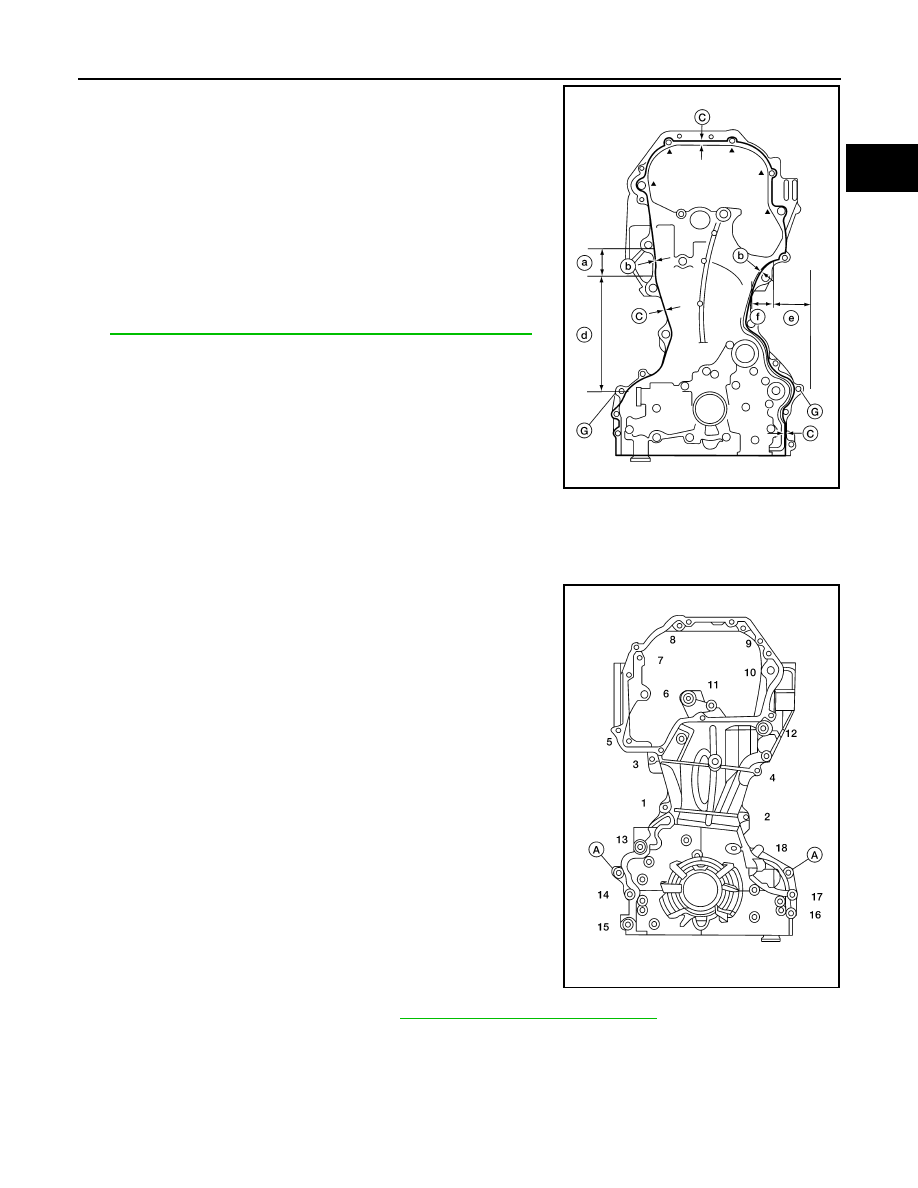
b. Apply a continuous bead of liquid gasket to front cover as

shown. 

Use Genuine RTV Silicone Sealant or equivalent. Refer to

GI-22, "Recommended Chemical Products and Sealants"

. 

CAUTION:

• Be sure sealant surfaces are free from grease, dirt, water,

and engine oil.

• Be sure to apply sealant without breaks or overlap.

• Installation should be done within 5 minutes after applica-

tion of liquid gasket.

• Do not fill the engine with engine oil for at least 30 min-

utes after the components are installed to allow the liquid

gasket to cure.

c. Make sure the mating marks on the timing chain and each sprocket are still aligned. Then install the front

cover.

CAUTION:

Do not damage the front oil seal during installation. 

d. Tighten front cover bolts in the numerical order shown.
e. After all bolts are tightened, retighten them to the specified

torque.

CAUTION:

Wipe off excess sealant leaking at the surface for installing

the oil pan.

10. Install the chain guide between the camshaft sprockets.

11. Install valve timing control cover. Refer to 

EM-80, "Valve Timing Control Cover"

12. Insert crankshaft pulley by aligning with crankshaft key. 

• Tap its center with a plastic hammer to insert. 

CAUTION:

• Do not hit belt mounting section with hammer to avoid breaking belt guide.

• Be sure not to damage front oil seal while installing crankshaft pulley.

(a)

: 35.7 mm (1.406 in)

(b)

: 6.0 – 7.0 mm (0.236 – 0.276 in)

(c)

: 3.4 – 4.4 mm (0.134 – 0.173 in)

(d)

: 179.6 mm (7.07 in)

(e)

: 35.5 mm (1.398 in)

(f)

: 31.3 mm (1.232 in)

(G) : Dowel pin hole

ALBIA0943ZZ

Front cover bolts
Bolts 6, 10, 12

: 49 N·m (5.0 kg-m, 36 ft-lb)

Bolts (all remaining) : 12.8 N·m (1.3 kg-m, 9 ft-lb)
(A)

: Dowel pin

ALBIA0944ZZ

EM-58

< REMOVAL AND INSTALLATION >

TIMING CHAIN

13. Install crankshaft pulley bolt (1) and tighten to specification.

CAUTION:

• Apply anti-corrosive engine oil to threads of crankshaft

pulley bolt (1) and bolt bearing surface prior to installa-

tion.

• Secure crankshaft pulley (2) with suitable tool to tighten

the bolt.

14. Apply a paint mark (A) on the front cover, mating with any one of six easy to recognize stamp marks on

bolt flange (B). 

15. Installation of the remaining components is in the reverse order of removal.

Step 1

: Crankshaft bolt (1) : 42.1 N·m (4.3 kg-m, 

31 ft-lb)

Step 2

: Crankshaft bolt (1) : 60

° + 6°

ALBIA0862GB

CYLINDER HEAD

EM-59

< REMOVAL AND INSTALLATION >

C

D

E

F

G

H

I

J

K

L

M

A

EM

N

P

O

CYLINDER HEAD

Exploded View

INFOID:0000000011279962

Removal and Installation

INFOID:0000000011279963

REMOVAL

1. Remove the timing chain. Refer to 

EM-50, "Removal and Installation"

.

2. Remove the camshafts. Refer to 

EM-69, "Removal and Installation"

.

3. Remove spark plugs. Refer to 

EM-19, "Removal and Installation"

.

4. Remove the intake manifold. Refer to 

EM-29, "Removal and Installation"

.

5. Remove the exhaust manifold and three way catalyst. Refer to 

EM-32, "Removal and Installation"

.

6. Loosen the cylinder head bolts in the reverse order shown,

using power tool. 

7. Remove cylinder head.
8. Remove cylinder head gasket.

INSPECTION AFTER REMOVAL

Outer Diameter of Cylinder Head Bolts

1. Cylinder head

2. Cylinder head gasket

A. Refer to INSTALLATION

AWBIA1921ZZ

: Engine front

AWBIA1922ZZ

EM-60

< REMOVAL AND INSTALLATION >

CYLINDER HEAD

• Replace the cylinder head bolts with new ones if the size differ-

ence between d1 and d2 exceeds the limit.

• If reduction of outer diameter appears in a position other than d2,

use it as d2 point.

INSTALLATION

1. Clean surfaces of cylinder head and cylinder block.
2. Install a new cylinder head gasket.

CAUTION:

Do not reuse cylinder head gasket.

3. Install the cylinder head.
4. Follow the steps below to tighten the cylinder head bolts in the numerical order as shown.

• Clean threads and seating surfaces of bolts.

• Apply new engine oil to the threads and the seating surfaces of bolts.

CAUTION:

• If cylinder head bolts are re-used, check their outer diameters before installation. Follow the

Outer Diameter of Cylinder Head Bolts measurement procedure.

• Check and confirm the tightening angle by using angle

wrench or protractor. Do not judge angle by visual inspec-

tion.

5. Installation of the remaining components is in the reverse order of removal. 

Limit (d1 - d2)

: 0.23 mm (0.0091 in) or more

AWBIA1923ZZ

Tool number (A)

: KV10112100 (BT-8653-A)

PBIC3208J

Step a

: 50 N·m (5.1 kg-m, 37 ft-lb) in order

Step b

: 60

° clockwise in order 

Step c

: Loosen to 0 N·m in order

Step d

: 39.2 N·m (4.0 kg-m, 29 ft-lb) in order

Step e

: 75

° clockwise in order 

Step f

: 75

° clockwise in order

: Engine front

AWBIA1922ZZ


Content   ..  571  572  573  574   ..