Nissan Rogue. Manual - part 571
TIMING CHAIN
EM-49
< REMOVAL AND INSTALLATION >
C
D
E
F
G
H
I
J
K
L
M
A
EM
N
P
O
TIMING CHAIN
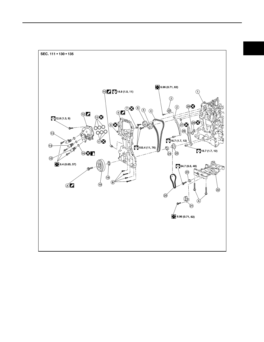
Exploded View
INFOID:0000000011279960
1.
Cylinder block
2.
Timing chain slack guide
3.
Chain tensioner
4.
Timing chain
5.
Camshaft sprocket (EXH)
6.
Camshaft sprocket (INT)
7.
Oil filter
8.
Front cover
9.
O-ring
10. Oil pressure sensor
11. Valve timing control cover O-rings
12. Valve timing control cover
13. Intake valve timing intermediate lock
control solenoid valve
14. Intake valve timing control solenoid
valve
15. Exhaust valve timing control so-
lenoid valve
16. Valve timing control solenoid valve O-
rings
17. Valve timing control cover O-rings
18. Front oil seal
19. Crankshaft pulley
20. Balancer unit timing chain
21. Balancer unit timing chain ten-
sioner
22. Balancer unit
23. Balancer unit sprocket
24. Oil pump drive spacer
25. Crankshaft sprocket
26. Timing chain tension guide
27. O-ring
AWBIA2090ZZ