Nissan Rogue. Manual - part 410


  Index      Nissan     Nissan Rogue (2015 year) - Service and Repair Manual


Search            


Content   ..  408  409  410  411   ..


Nissan Rogue. Manual - part 410


DLN-84

< UNIT DISASSEMBLY AND ASSEMBLY >

[TRANSFER: TY21C]

DRIVE PINION

5. Remove drive pinion from pinion bearing assembly using suit-

able tool (A) and suitable tool (B).

6. Remove adjusting shim.
7. Remove companion flange.
8. Remove the dust cover.
9. Remove the oil seal.
10. Perform inspection after disassembly. Refer to 

DLN-89, "Inspec-

tion"

.

Assembly

INFOID:0000000011278375

1. Select drive pinion adjusting shim. Refer to 

DLN-85, "Adjustment"

.

2. Assemble the selected drive pinion adjusting shim to drive pinion.
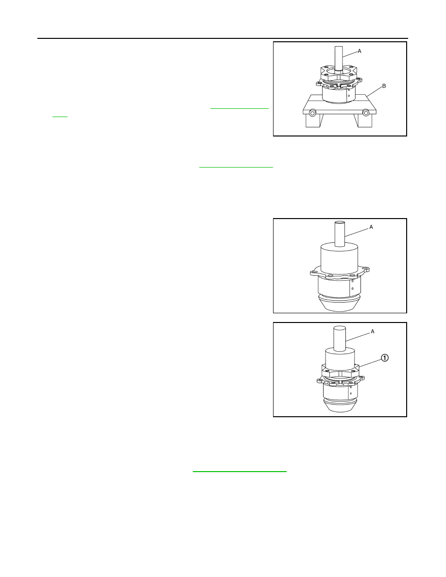
3. Install the drive pinion to pinion bearing assembly using suitable tool.

CAUTION:

• Do not reuse pinion bearing assembly.

• Apply gear oil to pinion bearing part.

4. Install oil seal to pinion bearing assembly using suitable tool (A).

CAUTION:

• Do not reuse the oil seal.

• When installing, do not incline oil seal.

• Apply multi-purpose grease onto oil seal lips, and gear oil

onto the circumference of the oil seal.

5. Install dust cover.

NOTE:

Tighten dust cover together with pinion bearing assembly.

6. Install companion flange (1) to pinion bearing using suitable tool

(A).

7. Apply anti-corrosive oil to the thread and seat of the lock nut,

and adjust the pinion lock nut tightening torque and pinion bear-

ing preload torque, using a preload gauge.

a. Install pinion lock nut, and then tighten to the specified torque.

CAUTION:

• Do not reuse pinion lock nut.

• Check that pinion lock nut is seated on the companion flange.

b. After tightening pinion lock nut to the specified torque, retighten the pinion lock nut by 25 degrees.
c.

Measure the pinion bearing preload.

8. Apply multi-purpose grease lightly and evenly onto an O-ring, and install it to the pinion bearing assembly.

CAUTION:

• Do not reuse O-ring.

• When installing O-ring, do not use a suitable tool.

• Do not damage O-ring.

JSDIA3953ZZ

JSDIA3996ZZ

Pinion lock nut 
tightening torque

: 90

±9 N·m (9.2±0.92kg-m, 66±7 ft-lb) 

Pinion bearing preload

: Refer to 

DLN-94, "Preload Torque"

.

JSDIA3997ZZ

DRIVE PINION

DLN-85

< UNIT DISASSEMBLY AND ASSEMBLY >

[TRANSFER: TY21C]

C

E

F

G

H

I

J

K

L

M

A

B

DLN

N

O

P

9. Install drive pinion assembly, and apply anti-corrosive oil onto

thread and seats on the mounting bolts. Tighten to the specified

torque.

NOTE:

Tighten dust cover together with pinion bearing assembly.

10. Check backlash, tooth contact, total preload and companion

flange runout. Refer to 

DLN-85, "Adjustment"

.

CAUTION:

Measure the total preload without oil seals of transfer cover

and transfer case.

Adjustment

INFOID:0000000011278376

ADJUSTING SHIM SELECTION

Measurement point

Select adjusting shim of T1, T2, and T3, respectively, by using the following equation.

T1 [Ring gear bearing adjusting shim (transfer case side)]

• T1  =  A 

−(B +X/2) +C +W −V −F −(M/100) +0.071 mm (0.0028 in)

JSDIA3951ZZ

JSDIA4034ZZ

DLN-86

< UNIT DISASSEMBLY AND ASSEMBLY >

[TRANSFER: TY21C]

DRIVE PINION

T2 [Ring gear bearing adjusting shim (transfer cover side)]

• T2  = 

−Y +Z +(B +X/2) −C −D −H +(M/100) +0.071 mm (0.0028 in)

T3 (Drive pinion adjusting shim)

• T3  = 

−Q +(R +S/2) −K +(O/100)

• Check dimension (M) on the ring gear side face.

NOTE:

Dimension “M” indicates the difference between the optimum

engagement and standard dimensions in increments of 0.01 mm

(0.0004 in) written on the ring gear side face.

• Check dimension (O) on the gear end of drive pinion.

NOTE:

Dimension “O” indicates the difference between the optimum

engagement and the standard dimensions in increments of 0.01

mm (0.0004 in) written on the gear end of drive pinion.

PINION BEARING PRELOAD

CAUTION:

When measuring preload, the rotating speed must be set to 30 rpm.
1. Remove ring gear shaft assembly from the transfer case. Refer to 

DLN-78, "Disassembly"

.

2. Rotate the companion flange back and forth from 2 to 3 times to check for unusual noise, binding, sticking,

and so on.

3. Rotate the companion flange at least 20 times to check for smooth operation of the bearing.
4. Measure the pinion bearing preload using Tool A).

CAUTION:

Each rotational part should rotate smoothly with the speci-

fied gear oil.

• If outside the standard, disassemble the drive pinion assembly

to check and adjust each part.

TOTAL PRELOAD

CAUTION:

When measuring preload, the rotating speed must be set to 30 rpm.
1. Measure pinion bearing preload.

CAUTION:

Check that the pinion bearing preload is within the standard.

2. Assemble the ring gear shaft assembly to the transfer case. Refer to 

DLN-79, "Assembly"

3. Install transfer cover to check and adjust each part. Refer to 

DLN-75, "Assembly"

.

4. Rotate the companion flange at least 20 times to check for smooth operation of the bearing.

JSDIA2495ZZ

JSDIA2496ZZ

Pinion bearing preload

: Refer to 

DLN-94, "Preload 

Torque"

.

Tool number

: ST3127S000 (J-25765-A)

JSDIA2500ZZ

DRIVE PINION

DLN-87

< UNIT DISASSEMBLY AND ASSEMBLY >

[TRANSFER: TY21C]

C

E

F

G

H

I

J

K

L

M

A

B

DLN

N

O

P

5. Measure the total preload using Tool (A).

CAUTION:

Each rotational part should rotate smoothly with the speci-

fied gear oil.

• If outside the standard, disassemble the transfer assembly to

check and adjust each part. Measure it with the transfer case

oil seal and transfer cover oil seal removed when measuring

total preload after disassembly. Then install transfer case oil seals and transfer cover oil seal.

BACKLASH

1. Install the bolt to the companion flange.
2. Fit a dial indicator onto the bolt (A).
3. Measure the circumference backlash of the companion flange.

• If outside the standard, disassemble the transfer assembly to

check and adjust each part.

TOOTH CONTACT

1. Remove transfer cover. Refer to 

DLN-74, "Disassembly"

.

2. Remove ring gear shaft assembly from transfer case. Refer to 

DLN-78, "Disassembly"

.

3. Apply red lead onto the ring gear.

CAUTION:

Apply red lead to both faces of 3 to 4 gears at 4 locations

evenly spaced on the ring gear.

4. Assemble the ring gear shaft assembly to the transfer case.

Refer to 

DLN-79, "Assembly"

.

5. Install transfer cover to check and adjust each part. Refer to

DLN-75, "Assembly"

.

NOTE:

At this timing, O-ring installing to transfer cover is not necessary.

Install O-ring after backlash and tooth contact are checked.

6. Remove the plug from the transfer case.
7. Rotate the companion flange back and forth several times, and check the drive pinion gear to ring gear

tooth contact by viewing from the plug hole.

Total preload

: Refer to 

DLN-94, "Preload 

Torque"

.

Tool number

: ST3127S000 (J-25765-A)

JSDIA2500ZZ

Backlash

: Refer to 

DLN-94, "Backlash"

.

JSDIA2501ZZ

JSDIA2188ZZ


Content   ..  408  409  410  411   ..