Nissan Rogue. Manual - part 252
DAS
REAR VIEW CAMERA WASHER CONTROL UNIT
DAS-179
< REMOVAL AND INSTALLATION >
[DRIVER ASSISTANCE SYSTEM]
C
D
E
F
G
H
I
J
K
L
M
B
N
P
A
REAR VIEW CAMERA WASHER CONTROL UNIT
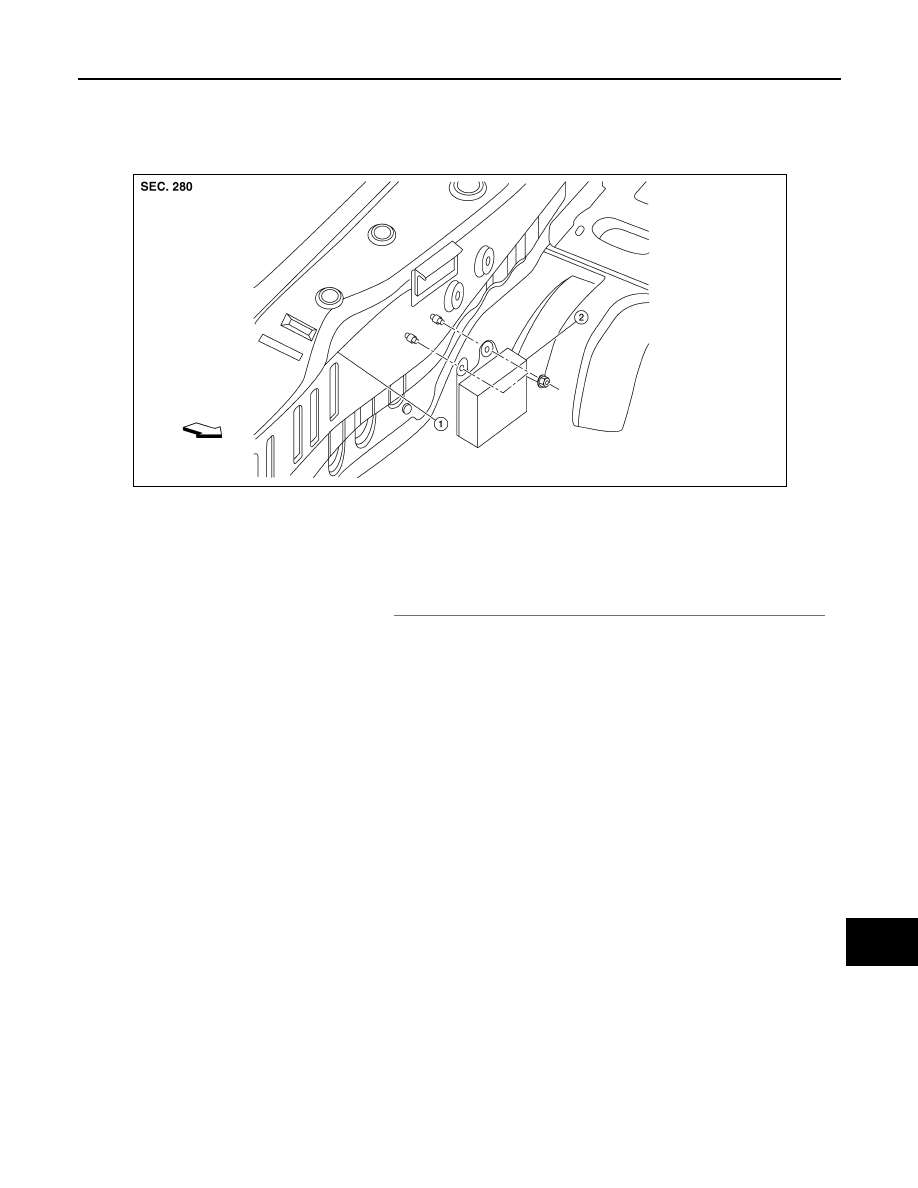
Exploded View
INFOID:0000000011277348
Removal and Installation
INFOID:0000000011277349
REMOVAL
1. Remove the luggage rear plate. Refer to
INT-37, "LUGGAGE REAR PLATE : Removal and Installation"
2. Disconnect the harness connector from the rear view camera washer control unit.
3. Remove the rear view camera washer control unit nuts.
4. Remove the rear view camera washer control unit.
INSTALLATION
Installation is in the reverse order of removal.
1.
Body panel
2.
Rear view camera washer control unit
ALOIA0240ZZ