Nissan Rogue. Manual - part 251
DAS
WARNING SYSTEMS BUZZER
DAS-175
< REMOVAL AND INSTALLATION >
[DRIVER ASSISTANCE SYSTEM]
C
D
E
F
G
H
I
J
K
L
M
B
N
P
A
WARNING SYSTEMS BUZZER
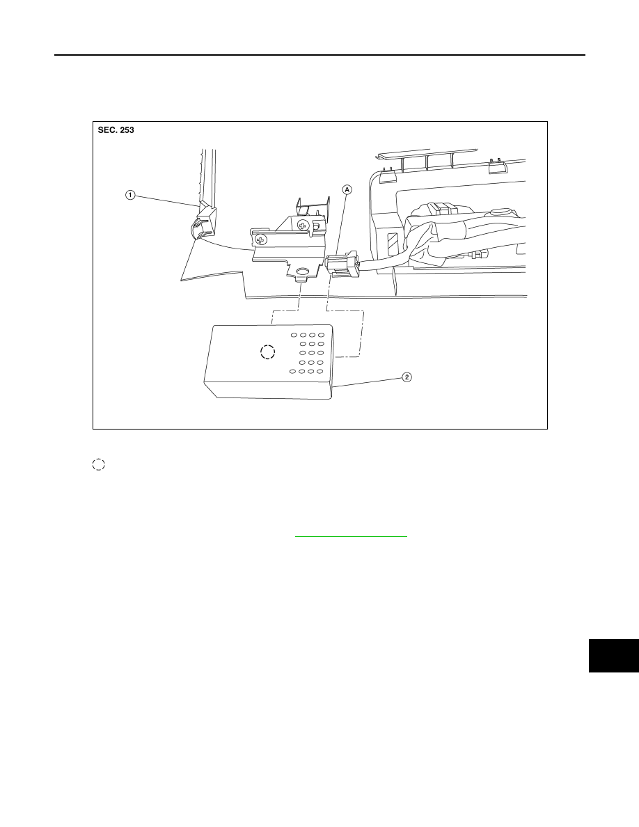
Exploded View
INFOID:0000000011277341
Removal and Installation
INFOID:0000000011277342
REMOVAL
1. Remove instrument lower panel LH. Refer to
2. Remove warning systems buzzer from bracket on the back of the instrument lower panel LH.
INSTALLATION
Installation is in the reverse order of removal.
1.
Instrument lower panel LH
2.
Warning systems buzzer
A. Harness connector
Pawl
AWOIA0075ZZ