Nissan Rogue. Manual - part 180


  Index      Nissan     Nissan Rogue (2015 year) - Service and Repair Manual


Search            


Content   ..  178  179  180  181   ..


Nissan Rogue. Manual - part 180


WHEEL SENSOR

BRC-131

< REMOVAL AND INSTALLATION >

[VDC/TCS/ABS]

C

D

E

G

H

I

J

K

L

M

A

B

BRC

N

O

P

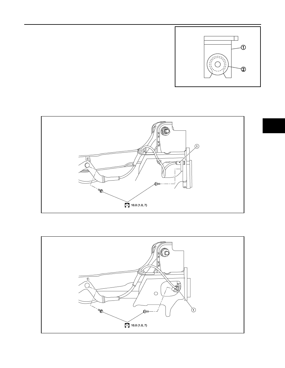
• Do not twist front wheel sensor harness when installing front

wheel sensor. Check that grommet (2) is fully inserted to

bracket (1). Check that front wheel sensor harness is not

twisted after installation.

REAR WHEEL SENSOR
REAR WHEEL SENSOR : Exploded View

INFOID:0000000011280672

FWD

AWD

JPFIC0209ZZ

ALFIA0415ZZ

1.

Rear LH wheel sensor 

ALFIA0416ZZ

1.

Rear LH wheel sensor

BRC-132

< REMOVAL AND INSTALLATION >

[VDC/TCS/ABS]

WHEEL SENSOR

REAR WHEEL SENSOR : Removal and Installation

INFOID:0000000011280673

CAUTION:

• Be careful not to damage rear wheel sensor edge and sensor rotor teeth.

• When removing the rear wheel hub and bearing, first remove the rear wheel sensor from the rear

wheel hub and bearing (FWD) or the rear axle housing (AWD). Failure to do so may result in damage

to the rear wheel sensor making the rear wheel sensor inoperative.

• Pull out the rear wheel sensor, being careful to turn it as little as possible. Do not pull on the rear

wheel sensor harness.

• Before installation, check if foreign objects such as iron fragments are adhered to the pick-up part of

the rear wheel sensor or to the inside of the hole in the rear wheel hub and bearing (FWD) or the rear

axle housing (AWD) for the rear wheel sensor, or if a foreign object is caught in the surface of the

sensor rotor. Fix as necessary and then install the rear wheel sensor.

REMOVAL

1. Remove the rear wheel and tire using power tool. Refer to 

WT-64, "Adjustment"

.

2. Remove the rear wheel sensor bolt.
3. Disconnect the harness connector from the rear wheel sensor. 
4. Remove the rear wheel sensor from the wheel hub and bearing (FWD) or the rear axle housing (AWD). 
5. Remove the rear wheel sensor harness grommet from the bracket.
6. Remove the bolt, the rear wheel sensor harness, and the rear wheel sensor from the bracket. 

INSTALLATION

Installation is in the reverse order of removal.

CAUTION:

• When installing, make sure there is no foreign material such as iron chips on and in the hole in the

rear wheel hub and bearing (FWD) or the rear axle housing (AWD) for the rear wheel sensor. Make

sure no foreign material has been caught in the sensor rotor. Remove any foreign material and clean

the mount.

• Do not twist rear wheel sensor harness when installing rear

wheel sensor. Check that grommet (2) is fully inserted to

bracket (1). Check that rear wheel sensor harness is not

twisted after installation.

JPFIC0209ZZ

SENSOR ROTOR

BRC-133

< REMOVAL AND INSTALLATION >

[VDC/TCS/ABS]

C

D

E

G

H

I

J

K

L

M

A

B

BRC

N

O

P

SENSOR ROTOR

FRONT SENSOR ROTOR
FRONT SENSOR ROTOR : Removal and Installation - Front Sensor Rotor

INFOID:0000000011280674

The front wheel sensor rotor is an integral part of the wheel hub and bearing and cannot be disassembled.

Refer to 

FAX-9, "Removal and Installation"

 (FWD) or 

FAX-47, "Removal and Installation"

 (AWD).

REAR SENSOR ROTOR
REAR SENSOR ROTOR : Removal and Installation - Rear Sensor Rotor

INFOID:0000000011280675

For FWD vehicles, the rear wheel sensor rotor is an integral part of the wheel hub and bearing and cannot be

disassembled. Refer to 

RAX-7, "Removal and Installation"

 (FWD).

For AWD vehicles, the rear wheel sensor rotor is pressed on the rear drive shaft and can be disassembled.

Refer to 

RAX-21, "Disassembly and Assembly"

 (AWD).

BRC-134

< REMOVAL AND INSTALLATION >

[VDC/TCS/ABS]

ABS ACTUATOR AND ELECTRIC UNIT (CONTROL UNIT)

ABS ACTUATOR AND ELECTRIC UNIT (CONTROL UNIT)

Exploded View

INFOID:0000000011280676

Removal and Installation

INFOID:0000000011280677

REMOVAL

CAUTION:

• To remove brake tube, use a flare nut wrench to prevent flare nuts and brake tube from being dam-

aged. 

• Do not remove actuator by holding harness.

NOTE:

When removing components such as hoses, tubes/lines, etc., cap or plug openings to prevent fluid from spill-

ing.
1. Disconnect negative battery terminal. Refer to 

PG-78, "Exploded View"

.

2. Remove the cowl top cover and cowl top extension. Refer to 

EXT-25, "Removal and Installation"

.

3. Separate brake tubes from ABS actuator and electric unit (control unit). Refer to 

BR-22, "FRONT :

Exploded View"

.

4. Remove the brake booster vacuum hose. Refer to 

BR-33, "Removal and Installation"

.

5. Separate the brake booster vacuum tube and place aside. Refer to 

BR-23, "FRONT : Removal and Instal-

lation"

.

6. Disconnect the harness connector from the ABS actuator and electric unit (control unit).
7. Remove ABS actuator and electric unit (control unit) bracket bolts and bushings.
8. Remove ABS actuator and electric unit (control unit) from vehicle.

INSTALLATION

Installation is in the reverse order of removal.

1.

ABS actuator and electric unit (control unit) 2.

Connector

3. Bracket

A. To front LH brake caliper

B. To rear RH brake caliper

C. From master cylinder secondary side

D. From master cylinder primary side

E. To rear LH brake caliper

F. To front RH brake caliper

AWFIA1079ZZ


Content   ..  178  179  180  181   ..