Nissan Rogue. Manual - part 143
BR-42
< REMOVAL AND INSTALLATION >
FRONT DISC BRAKE
5. Depress the brake pedal several times.
6. Check the drag of front disc brake again. If any drag is found, disassemble the brake caliper body.
7. Burnish contact surfaces after refinishing or replacing disc brake rotors or if a soft pedal occurs at very low
mileage. Refer to
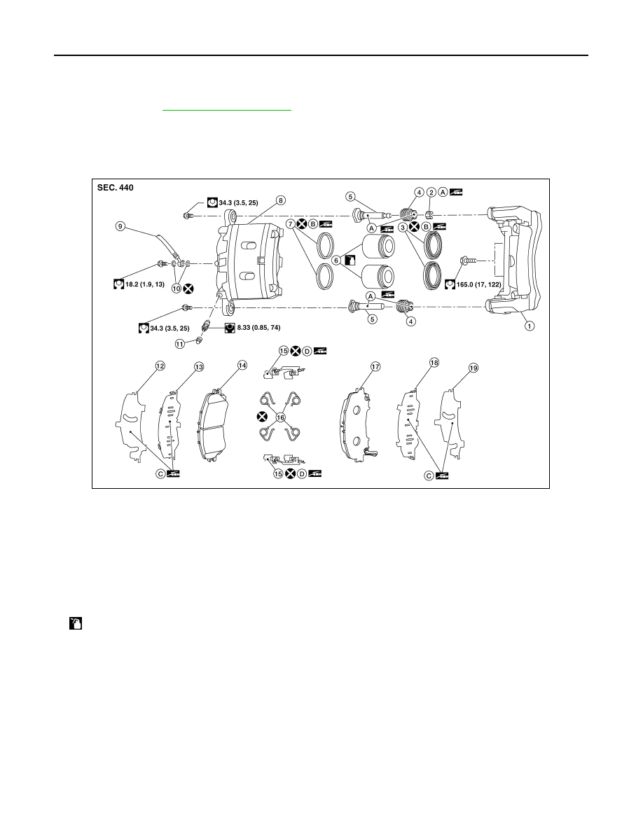
BRAKE CALIPER ASSEMBLY (2 PISTON TYPE)
BRAKE CALIPER ASSEMBLY (2 PISTON TYPE) : Exploded View
INFOID:0000000011279893
BRAKE CALIPER ASSEMBLY (2 PISTON TYPE) : Removal and Installation
INFOID:0000000011279894
WARNING:
Clean dust on brake caliper and brake pad with a vacuum dust collector to minimize the hazard of air-
borne particles or other materials.
CAUTION:
• Do not depress the brake pedal.
• Do not spill or splash brake fluid on painted areas; it may cause paint damage. If brake fluid is
splashed on painted areas, wash it away with water immediately.
• Do not bend, twist or pull the brake hoses and piping.
• Do not reuse drained brake fluid.
NOTE:
1.
Torque member
2.
Bushing
3.
Piston boot
4.
Slide pin boot
5.
Slide pin
6.
Piston
7.
Piston seal
8.
Brake caliper body
9.
Bleeder cap
10. Brake hose
11. Copper sealing washers
12. Inner shim cover
13. Inner shim
14. Inner pad
15. Pad retainer
16. Anti-rattle clip
17. Outer pad
18. Outer shim
19. Outer shim cover
A.
Niglube Rx-2
B.
Rubber grease
C.
Molykote® AS-880N
D.
Molykote® 7439
: Apply brake fluid.
AWFIA1114ZZ