Nissan Rogue. Manual - part 1161


  Index      Nissan     Nissan Rogue (2015 year) - Service and Repair Manual


Search            


Content   ..  1159  1160  1161  1162   ..


Nissan Rogue. Manual - part 1161


TM-16

< SYSTEM DESCRIPTION >

[CVT: RE0F10D]

COMPONENT PARTS

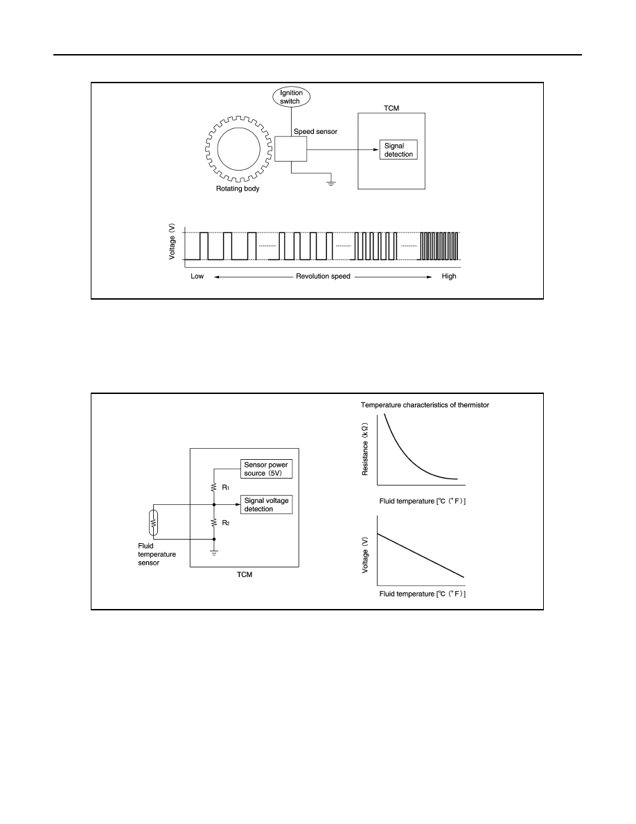
• The input speed sensor generates an ON-OFF pulse signal according to the rotating body speed. TCM

judges the rotating body speed from the pulse signal.

CVT CONTROL SYSTEM : CVT Fluid Temperature Sensor

INFOID:0000000011279251

• The CVT fluid temperature sensor is installed to control valve.

• The CVT fluid temperature sensor detects CVT fluid temperature in oil pan.

• The fluid temperature sensor uses a thermistor, and changes the signal voltage by converting changes in the

CVT fluid temperature to a resistance value. TCM evaluates the CVT fluid temperature from the signal volt-

age value. 

CVT CONTROL SYSTEM : Primary Pressure Sensor

INFOID:0000000011279252

• The primary pressure sensor is installed to control valve.

• The primary pressure sensor detects the pressure applied to the primary pulley. 

JSDIA1824GB

JSDIA1825GB

COMPONENT PARTS

TM-17

< SYSTEM DESCRIPTION >

[CVT: RE0F10D]

C

E

F

G

H

I

J

K

L

M

A

B

TM

N

O

P

• When pressure is applied to the ceramic device in the primary pressure sensor, the ceramic device is

deformed, resulting in voltage change. TCM evaluates the primary pressure from its voltage change. Voltage

is increased along with pressure increase. 

CVT CONTROL SYSTEM : Secondary Pressure Sensor

INFOID:0000000011279253

• The secondary pressure sensor is installed to control valve.

• The secondary pressure sensor detects the pressure applied to the secondary pulley. 

• When pressure is applied to the metal diaphragm in the secondary pressure sensor, the metal diaphragm is

deformed, resulting in voltage change. TCM evaluates the secondary pressure from its voltage change. Volt-

age is increased along with pressure increase. 

CVT CONTROL SYSTEM : Primary Pressure Solenoid Valve

INFOID:0000000011279254

• The primary pressure solenoid valve is installed to control valve.

• The primary pressure solenoid valve controls the primary reducing valve. For information about the primary

reducing valve, refer to 

TM-27, "TRANSAXLE : Component Description"

.

• The primary pressure solenoid valve uses the linear solenoid valve

[N/H (normal high) type].

NOTE:

• The principle of the linear solenoid valve utilizes the fact that the

force pressing on the valve spool installed inside the coil

increases nearly in proportion to the current. This allows it to pro-

duce a fluid pressure that is proportional to this pressing force.

• The N/H (normal high) produces hydraulic control when the coil

is not energized.

JSDIA1831GB

JSDIA1831GB

JSDIA3647GB

TM-18

< SYSTEM DESCRIPTION >

[CVT: RE0F10D]

COMPONENT PARTS

CVT CONTROL SYSTEM : Secondary Pressure Solenoid Valve

INFOID:0000000011279255

• The secondary pressure solenoid valve is installed to control valve.

• The secondary pressure solenoid valve controls the secondary reducing valve. For information about the

secondary reducing valve, refer to 

TM-27, "TRANSAXLE : Component Description"

.

• The secondary pressure solenoid valve uses the linear solenoid

valve [N/H (normal high) type].

NOTE:

• The principle of the linear solenoid valve utilizes the fact that the

force pressing on the valve spool installed inside the coil

increases nearly in proportion to the current. This allows it to pro-

duce a fluid pressure that is proportional to this pressing force.

• The N/H (normal high) produces hydraulic control when the coil

is not energized.

CVT CONTROL SYSTEM : Select Solenoid Valve

INFOID:0000000011279256

• The select solenoid valve is installed to control valve.

• The select solenoid valve adjusts the forward clutch engaging pressure and the reverse brake engaging

pressure. For information about the forward clutch and reverse brake, refer to 

TM-27, "TRANSAXLE : Com-

ponent Description"

.

• The select solenoid valve uses the linear solenoid valve [N/H (nor-

mal high) type].

NOTE:

• The principle of the linear solenoid valve utilizes the fact that the

force pressing on the valve spool installed inside the coil

increases nearly in proportion to the current. This allows it to pro-

duce a fluid pressure that is proportional to this pressing force.

• The N/H (normal high) type produces hydraulic control when the

coil is not energized.

CVT CONTROL SYSTEM : Torque Converter Clutch Solenoid Valve

INFOID:0000000011279257

• The torque converter clutch solenoid valve is installed to control valve.

• The torque converter clutch solenoid valve controls the torque converter clutch control valve. For information

about the torque converter clutch control valve, refer to 

TM-27, "TRANSAXLE : Component Description"

.

• The torque converter clutch solenoid valve utilizes a linear sole-

noid valve [N/L (normal low) type].

NOTE:

• The principle of the linear solenoid valve utilizes the fact that the

force pressing on the valve spool installed inside the coil

increases nearly in proportion to the current. This allows it to pro-

duce a fluid pressure that is proportional to this pressing force.

• The N/L (normal low) type does not produce hydraulic control

when the coil is not energized.

CVT CONTROL SYSTEM : Line Pressure Solenoid Valve

INFOID:0000000011279258

• The line pressure solenoid valve is installed to control valve.

• The line pressure solenoid valve controls the pressure regulator valve. For information about the pressure

regulator valve, refer to 

TM-27, "TRANSAXLE : Component Description"

.

JSDIA3647GB

JSDIA3647GB

JSDIA3648GB

COMPONENT PARTS

TM-19

< SYSTEM DESCRIPTION >

[CVT: RE0F10D]

C

E

F

G

H

I

J

K

L

M

A

B

TM

N

O

P

• The line pressure solenoid valve uses the linear solenoid valve [N/

H (normal high) type].

NOTE:

• The principle of the linear solenoid valve utilizes the fact that the

force pressing on the valve spool installed inside the coil

increases nearly in proportion to the current. This allows it to pro-

duce a fluid pressure that is proportional to this pressing force.

• The N/H (normal high) produces hydraulic control when the coil

is not energized.

CVT CONTROL SYSTEM : Overdrive Control Switch

INFOID:0000000011279259

• The overdrive control switch   is installed to the shift selector

knob.

• When the O/D OFF indicator lamp on the combination meter is

OFF and the overdrive control switch is pressed, the O/D OFF is

active and the O/D OFF indicator lamp is ON.

• When the O/D OFF indicator lamp on the combination meter is ON

and the overdrive control switch is pressed, the O/D OFF is can-

celled and the O/D OFF indicator lamp is OFF.

CVT CONTROL SYSTEM : O/D OFF Indicator Lamp

INFOID:0000000011279260

DESIGN/PURPOSE

The O/D OFF indicator lamp notifies the driver that the shift control

of transaxle is in O/D OFF.

BULB CHECK

For two seconds after the ignition switch is turned ON.

SYSTEM DIAGRAM

SIGNAL PATH

• When overdrive control switch signal is input to the combination meter, the combination meter transmits the

overdrive control switch signal to the TCM via CAN communication.

JSDIA3647GB

JSDIA3881ZZ

JPNIA1891ZZ

JSDIA5403GB


Content   ..  1159  1160  1161  1162   ..