Nissan Rogue. Manual - part 1162


  Index      Nissan     Nissan Rogue (2015 year) - Service and Repair Manual


Search            


Content   ..  1160  1161  1162  1163   ..


Nissan Rogue. Manual - part 1162


TM-20

< SYSTEM DESCRIPTION >

[CVT: RE0F10D]

COMPONENT PARTS

• When all of the following conditions are satisfied, the TCM transmits OD OFF indicator lamp signal to the

combination meter via CAN communication. The combination meter turns ON the O/D OFF indicator lamp

on the combination meter, according to the signal.

- TCM receives overdrive control switch via CAN communication from combination meter.

- Selector lever: D position.

LIGHTING CONDITION

When all of the following conditions are satisfied.

• Ignition switch: ON

• Selector lever: D position

• Overdrive control switch is pressed when the O/D OFF indicator lamp is OFF.

SHUTOFF CONDITION

When any of the conditions listed below is satisfied.

• Ignition switch: Other than ON

• Overdrive control switch is pressed when the O/D OFF indicator lamp is ON.

• Selector lever is shifted to other than D position when the O/D OFF indicator lamp is ON.

CVT CONTROL SYSTEM : Shift Position Indicator

INFOID:0000000011279261

TCM transmits shift position signal to combination meter via CAN communication. The actual shift position is

displayed on combination meter according to the signal.

SHIFT LOCK SYSTEM
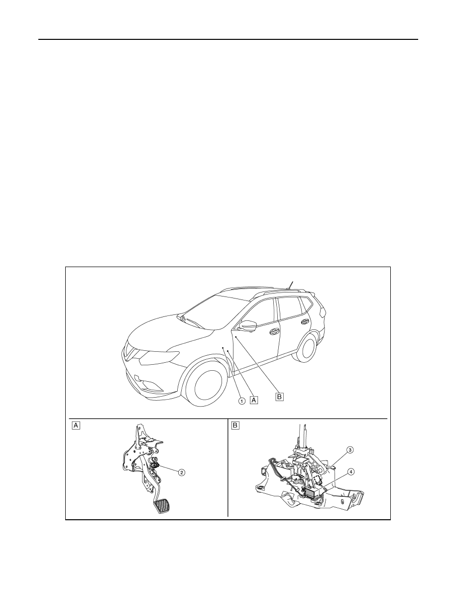
SHIFT LOCK SYSTEM : Component Parts Location

INFOID:0000000011279262

COMPONENT DESCRIPTION

A

Brake pedal, upper

B

CVT shift selector assembly

ALDIA0551ZZ

COMPONENT PARTS

TM-21

< SYSTEM DESCRIPTION >

[CVT: RE0F10D]

C

E

F

G

H

I

J

K

L

M

A

B

TM

N

O

P

No.

Component

Function

1.

BCM

When the stop lamp switch signal is input to the BCM, the BCM outputs the shift lock solenoid 
operating signal.
Refer to 

BCS-7, "BODY CONTROL SYSTEM : Component Parts Location"

 for detailed instal-

lation location.

2.

Stop lamp switch

• The stop lamp switch turns ON when the brake pedal is depressed.
• When the stop lamp switch turns ON, the BCM is energized.

3.

Park position switch

The park position switch detects that the selector lever is in “P” position.

4.

Shift lock solenoid

The shift lock solenoid operates according to the signal from the BCM and moves the lock le-
ver.

TM-22

< SYSTEM DESCRIPTION >

[CVT: RE0F10D]

STRUCTURE AND OPERATION

STRUCTURE AND OPERATION

TRANSAXLE
TRANSAXLE : Cross-Sectional View

INFOID:0000000011279263

Converter housing 

Oil pump

Planetary gear

Control valve

Oil pan

Steel belt 

Primary pulley

Secondary pulley

Side cover

Transaxle case

Differential case

Final gear

Reduction gear

Idler gear

Output gear

Drive sprocket 

Torque converter

Driven sprocket

Oil pump chain 

FWD

AWD

JSDIA5169ZZ

STRUCTURE AND OPERATION

TM-23

< SYSTEM DESCRIPTION >

[CVT: RE0F10D]

C

E

F

G

H

I

J

K

L

M

A

B

TM

N

O

P

TRANSAXLE : Operation Status

INFOID:0000000011279264

×: Engaged or applied.

TRANSAXLE : Transaxle Mechanism

INFOID:0000000011279265

TORQUE CONVERTER (WITH LOCK-UP FUNCTION)

In the same way as a conventional A/T, the torque converter is a system that increases the engine torque and

transmits the torque to the transaxle. A symmetrical 3-element, 1-stage, 2-phase type is used here.

OIL PUMP

Utilizes a vane-type oil pump that is driven by the engine through the oil pump drive chain in order to increase

efficiency of pump discharge volume in low-speed zone and optimize pump discharge volume in high-speed

zone. Discharged oil from oil pump is transmitted to control valve. It is used as the oil of primary and second-

ary pulley operation, the oil of clutch operation, and the lubricant for each part.

PLANETARY GEAR

• A planetary gear type of forward/reverse selector mechanism is installed between the torque converter and

primary pulley.

• The power from the torque converter is input via the input shaft, operating a wet multi-plate clutch by means

of hydraulic pressure to switch between forward and reverse driving.

Operation of Planetary gear

BELT & PULLEY

It is composed of a pair of pulleys (the groove width is changed freely in the axial direction) and the steel belt

(the steel plates are placed continuously and the belt is guided with the multilayer steel rings on both sides).

Selector lever 

position

Parking mech-

anism

Forward 

clutch

Reverse brake  Primary pulley 

Secondary 

pulley

Steel belt

Final drive

P

×

R

×

×

×

×

×

N

D

×

×

×

×

×

L

×

×

×

×

×

JSDIA2426GB


Content   ..  1160  1161  1162  1163   ..