Nissan Rogue. Manual - part 1160


  Index      Nissan     Nissan Rogue (2015 year) - Service and Repair Manual


Search            


Content   ..  1158  1159  1160  1161   ..


Nissan Rogue. Manual - part 1160


TM-12

< SYSTEM DESCRIPTION >

[CVT: RE0F10D]

COMPONENT PARTS

SYSTEM DESCRIPTION

COMPONENT PARTS

CVT CONTROL SYSTEM
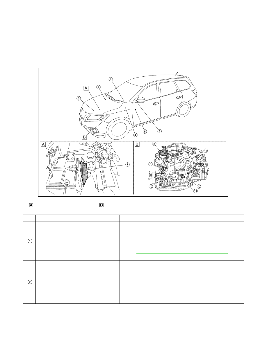
CVT CONTROL SYSTEM : Component Parts Location

INFOID:0000000011279245

Engine room, LH

Transaxle assembly

ALDIA0478ZZ

No.

Component

Function

Combination meter

Mainly transmits the following signal to TCM via CAN communication.
• Overdrive control switch signal
• SPORT mode switch signal
Mainly receives the following signals from TCM via CAN communication.
• O/D OFF indicator lamp signal
• Shift position signal
Refer to 

MWI-6, "METER SYSTEM : Component Parts Location"

 for de-

tailed installation location.

ABS actuator and electric unit (control unit)

Mainly transmits the following signal to TCM via CAN communication.
• ABS operation signal
• TCS operation signal
• VDC operation signal
• ABS malfunction signal
• Vehicle speed signal
• G sensor signal
Refer to 

BRC-7, "Component Parts Location"

 for detailed installation loca-

tion.

COMPONENT PARTS

TM-13

< SYSTEM DESCRIPTION >

[CVT: RE0F10D]

C

E

F

G

H

I

J

K

L

M

A

B

TM

N

O

P

*: These components are included in control valve assembly.

CVT CONTROL SYSTEM : TCM

INFOID:0000000011279246

• The TCM consists of a microcomputer and connectors for signal

input and output and for power supply.

• The vehicle driving status is judged based on the signals from the

sensors, switches, and other control units, and the optimal tran-

saxle control is performed.

• For TCM control items, refer to 

TM-31, "CVT CONTROL SYSTEM

: System Description"

.

ECM

Mainly transmits the following signal to TCM via CAN communication.
• Engine and CVT integrated control signal

NOTE:
General term for the communication (torque-down permission, torque-
down request, etc.) exchanged between the ECM and TCM.

• Engine speed signal
• Engine coolant temperature signal
• Accelerator pedal position signal
• Closed throttle position signal
Mainly receives the following signals from TCM via CAN communication.
• Malfunctioning indicator lamp signal
Refer to 

EC-14, "Component Parts Location"

 for detailed installation loca-

tion.

BCM

Mainly transmits the following signal to TCM via CAN communication.
• Stop lamp switch signal
Refer to 

BCS-7, "BODY CONTROL SYSTEM : Component Parts Location"


for detailed installation location.

SPORT mode switch

DMS-6, "SPORT Mode Switch"

ECO mode switch

DMS-22, "ECO Mode Switch"

Overdrive control switch

TM-19, "CVT CONTROL SYSTEM : Overdrive Control Switch"

TCM

TM-13, "CVT CONTROL SYSTEM : TCM"

Transmission range switch

TM-14, "CVT CONTROL SYSTEM : Transmission Range Switch"

Input speed sensor

TM-15, "CVT CONTROL SYSTEM : Input Speed Sensor"

CVT unit connector

Control 
valve

CVT fluid temperature sensor*

TM-16, "CVT CONTROL SYSTEM : CVT Fluid Temperature Sensor"

Primary pressure sensor*

TM-16, "CVT CONTROL SYSTEM : Primary Pressure Sensor"

Secondary pressure sensor*

TM-17, "CVT CONTROL SYSTEM : Secondary Pressure Sensor"

Line pressure solenoid valve*

TM-18, "CVT CONTROL SYSTEM : Line Pressure Solenoid Valve"

Primary pressure solenoid valve*

TM-17, "CVT CONTROL SYSTEM : Primary Pressure Solenoid Valve"

Secondary pressure solenoid valve*

TM-18, "CVT CONTROL SYSTEM : Secondary Pressure Solenoid Valve"

Torque converter clutch solenoid 
valve*

TM-18, "CVT CONTROL SYSTEM : Torque Converter Clutch Solenoid 

Valve"

Select solenoid valve*

TM-18, "CVT CONTROL SYSTEM : Select Solenoid Valve"

Primary speed sensor

TM-14, "CVT CONTROL SYSTEM : Primary Speed Sensor"

Output speed sensor

TM-15, "CVT CONTROL SYSTEM : Output Speed Sensor"

No.

Component

Function

JSDIA4183ZZ

TM-14

< SYSTEM DESCRIPTION >

[CVT: RE0F10D]

COMPONENT PARTS

CVT CONTROL SYSTEM : Transmission Range Switch

INFOID:0000000011279247

• The transmission range switch is installed to upper part of tran-

saxle case.

• The transmission range switch detects the selector lever position.

CVT CONTROL SYSTEM : Primary Speed Sensor

INFOID:0000000011279248

• The primary speed sensor is installed to side cover of transaxle.

• The primary speed sensor detects primary pulley speed.

• The primary speed sensor generates an ON-OFF pulse signal according to the rotating body speed. TCM

judges the rotating body speed from the pulse signal.

JSDIA4184ZZ

JSDIA3073ZZ

JSDIA1824GB

COMPONENT PARTS

TM-15

< SYSTEM DESCRIPTION >

[CVT: RE0F10D]

C

E

F

G

H

I

J

K

L

M

A

B

TM

N

O

P

CVT CONTROL SYSTEM : Output Speed Sensor

INFOID:0000000011279249

• The output speed sensor is installed to back side of transaxle.

• The output speed sensor detects final gear speed.

• The output speed sensor generates an ON-OFF pulse signal according to the rotating body speed. TCM

judges the rotating body speed from the pulse signal.

CVT CONTROL SYSTEM : Input Speed Sensor

INFOID:0000000011279250

• The input speed sensor is installed to the front side of transaxle

case.

• The input speed sensor detects input shaft speed. 

JSDIA3073ZZ

JSDIA1824GB

JSDIA3073ZZ


Content   ..  1158  1159  1160  1161   ..