Nissan Maxima. Manual - part 852


  Index      Nissan     Nissan Maxima (2009-2014 year) - Service and Repair Manual


Search            


Content   ..  850  851  852  853   ..


Nissan Maxima. Manual - part 852


MWI

METER SYSTEM

MWI-23

< SYSTEM DESCRIPTION >

C

D

E

F

G

H

I

J

K

L

M

B

A

O

P

WARNING LAMPS/INDICATOR LAMPS : Component Description

INFOID:0000000010049558

INFORMATION DISPLAY
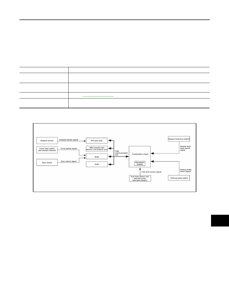
INFORMATION DISPLAY : System Diagram

INFOID:0000000010049559

INFORMATION DISPLAY : System Description

INFOID:0000000010049560

FUNCTION

The information display can indicate the following items.

• Outside air temperature

• Trip/fuel consumption readings

• Intelligent Key operation information

• Tire pressure information

• Maintenance information

• Warning/Indication messages (Door ajar, low fuel, low washer fluid, parking brake, cruise control, loose fuel

cap, check tire pressure)

OUTSIDE AIR TEMPERATURE INDICATION

The outside air temperature indication is displayed while the ignition switch is in the ON position.

Indication range is between -30 and 55

°C (-22 and 131°F). When outside temperature is less than 3°C (37°F),

display shows ICY. The indicated temperature is not affected by engine heat. It changes only when one of the

following conditions exists.

• When vehicle speed is more than approximately 20 km/h (12 MPH).

• The ignition switch has been turned OFF for more than 3.5 hours.

• When outside air temperature is less than the indicated temperature.

4.

TCM F15

5.

BCM M18, M19, M20, M21 (view with 
instrument panel removed)

6.

ABS actuator and electric unit (control 
unit) E26

7.

Fuel level sensor unit and fuel pump 
(fuel level sensor) B42 (view with rear 
seat and inspection hole cover re-
moved)
⇐: Front

8.

Oil pressure switch F41 (view with en-
gine removed)

9.

Parking brake switch E35 (view with in-
strument lower cover LH removed)

Unit

Description

Combination meter

Turns the oil pressure warning lamp ON/OFF according to the oil pressure switch signal received 
from BCM by means of communication. 

IPDM E/R

Reads the ON/OFF signals from the oil pressure switch and transmits the oil pressure switch signal 
to the combination meter via BCM with the CAN communication line. 

Oil pressure switch

Refer to 

MWI-42, "Description"

BCM

Transmits the oil pressure switch signal received from IPDM E/R via CAN communication to the 
combination meter via CAN communication. 

AWNIA2689GB

MWI-24

< SYSTEM DESCRIPTION >

METER SYSTEM

MPG

Average fuel consumption indication is calculated using vehicle speed signals from the ABS actuator and elec-

tric unit (control unit) and fuel consumption information from the ECM.

MPG/MPH

The average speed mode can be selected to display the average fuel consumption and average speed since

last reset. The indications are calculated using vehicle speed signals from the ABS actuator and electric unit

(control unit) and fuel consumption information from the ECM.

RANGE

The range indication provides the driver with an estimation of the distance that can be driven before refueling.

The range is calculated using signals from the fuel level sensor unit and fuel pump (fuel level sensor) (fuel

remaining), ECM (fuel consumption) and vehicle speed signals from the ABS actuator and electric unit (control

unit).

TIRE PRESSURE DISPLAY

Displays the individual tire pressure details. The BCM sends the tire pressure signals to the combination meter

via CAN communication lines.

DOOR AJAR WARNING

This warning appears when the Intelligent Key is in the vehicle and any door or the trunk is opened.

LOW FUEL WARNING

This warning appears when the fuel level in the fuel tank reaches approximately 12.3  (3 1/4 US gal, 2 3/4

Imp gal). A variable resistor signal is supplied to the combination meter from the fuel level sensor unit and fuel

pump (fuel level sensor) to determine the amount of fuel in the fuel tank.

LOOSE FUEL CAP WARNING

The LOOSE FUEL CAP indicator will display in the information display when the fuel-filler cap is not tightened

correctly. The indicator will turn off as soon as the ECM detects the fuel-filler cap is properly tightened. The

ECM provides a loose fuel cap signal to the combination meter via CAN communication lines.

CHECK TIRE PRESSURE WARNING

The CHECK TIRE PRESSURE indicator will display in the information display when BCM has detected a low

tire pressure condition. After 8 seconds, the Tire Pressure Warning Mode will flash and the low tire pressure

will be highlighted (one of the four numbers). These two screens will continue to toggle every eight seconds

until the low tire pressure condition has been corrected and the vehicle has been driven above 25 km/h (16

MPH).

LOW WINDSHIELD WASHER FLUID WARNING

This warning appears when the windshield washer fluid level is low. When the windshield washer fluid level is

low, the washer fluid level switch provides a ground signal to the combination meter (unified meter control

unit). The message will be displayed after the ignition switch is turned on for 3 minutes. Once fluid is added,

the message will stay on for 30 seconds and then turn off.

PARKING BRAKE INDICATOR

When the ignition switch is in the ON position and the parking brake is depressed, the indicator will turn on.

When the parking brake is depressed, the parking brake switch provides a ground signal to the combination

meter (unified meter control unit). Then, when the ignition switch is turned ON and vehicle speed is greater

than 5 km/h (3 MPH), the message is displayed.

CRUISE SET INDICATOR

The cruise set indicator message is displayed when the vehicle speed is controlled by the ASCD system. The

ECM provides an ASCD ON signal to the combination meter (unified meter control unit) via CAN communica-

tion lines.

MWI

METER SYSTEM

MWI-25

< SYSTEM DESCRIPTION >

C

D

E

F

G

H

I

J

K

L

M

B

A

O

P

INFORMATION DISPLAY : Component Parts Location

INFOID:0000000010049561

1.

Combination meter M23, M24

2.

IPDM E/R E17, E18, E201, F10

3.

ECM E10

AWNIA2477GB

MWI-26

< SYSTEM DESCRIPTION >

METER SYSTEM

INFORMATION DISPLAY : Component Description

INFOID:0000000010049562

4.

TCM F15

5.

BCM M18, M19, M20, M21 (view with 
instrument panel removed)

6.

ABS actuator and electric unit (control 
unit) E26

7.

Fuel level sensor unit and fuel pump 
(fuel level sensor) B42 (view with rear 
seat and inspection hole cover re-
moved)
⇐: Front

8.

Oil pressure switch F41 (view with en-
gine removed)

9.

Parking brake switch E35 (view with in-
strument lower cover LH removed)

Unit

Description

Combination meter

Controls the information display according to the signal received from each unit. 

Fuel level sensor unit and fuel 
pump (fuel level sensor)

Refer to 

MWI-40, "Description"

.

ECM

Transmits the following signals to the combination meter via CAN communication line.
• Engine speed signal
• Fuel consumption monitor signal
• Loose fuel cap signal

ABS actuator and electric unit 
(control unit)

Transmits the vehicle speed signal to the combination meter via CAN communication line.

BCM

Transmits signals provided by various units to the combination meter via CAN communication line.

Washer fluid level switch

Transmits the washer fluid level signal to the combination meter.

Parking brake switch

Refer to 

MWI-44, "Description"

.

Door switch

Transmits the door switch signals to BCM.

Trunk lamp switch and trunk 
release solenoid

Transmits the trunk switch signal to BCM.


Content   ..  850  851  852  853   ..