Nissan Maxima. Manual - part 850


  Index      Nissan     Nissan Maxima (2009-2014 year) - Service and Repair Manual


Search            


Content   ..  848  849  850  851   ..


Nissan Maxima. Manual - part 850


MWI

METER SYSTEM

MWI-15

< SYSTEM DESCRIPTION >

C

D

E

F

G

H

I

J

K

L

M

B

A

O

P

ENGINE COOLANT TEMPERATURE GAUGE : Component Description

INFOID:0000000010049542

FUEL GAUGE
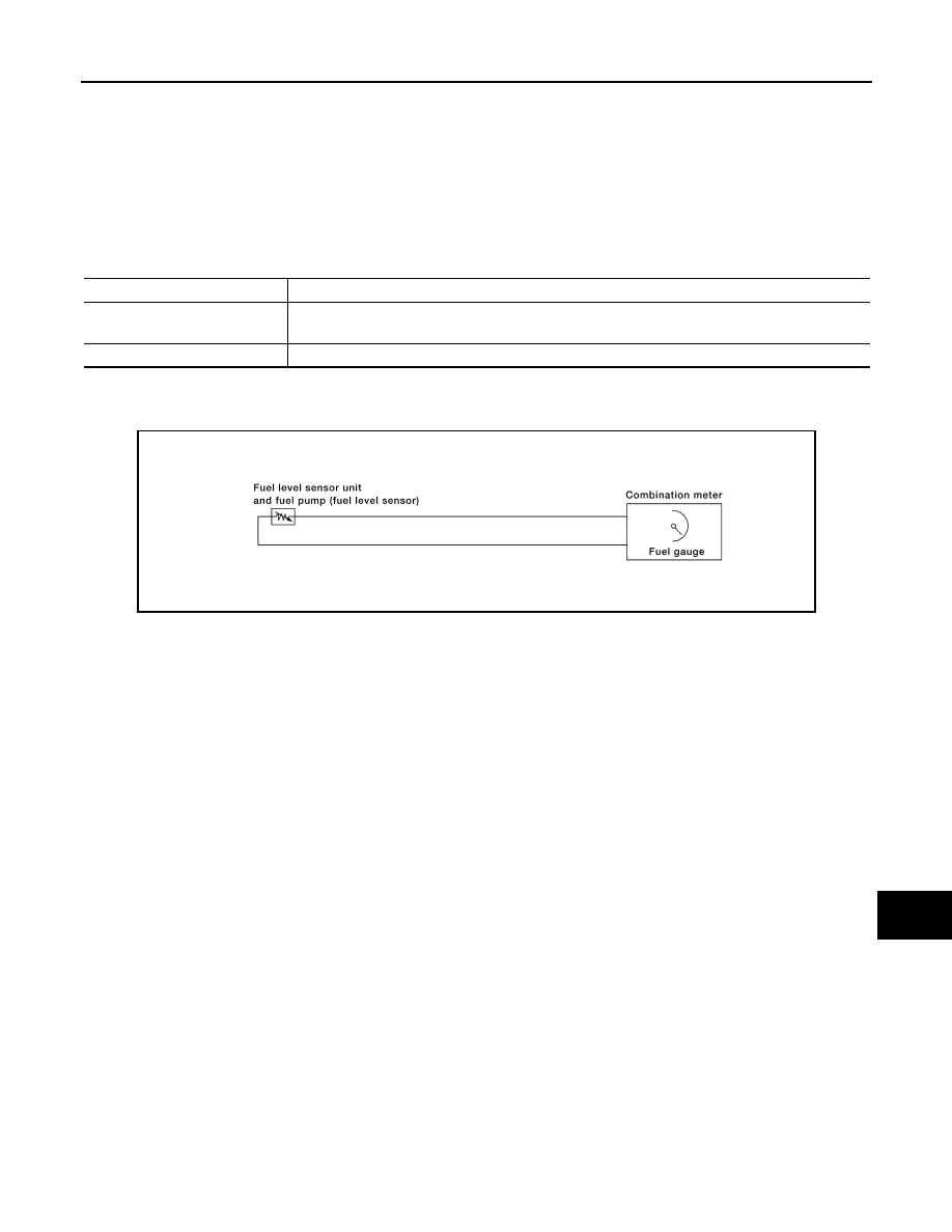
FUEL GAUGE : System Diagram

INFOID:0000000010049543

FUEL GAUGE : System Description

INFOID:0000000010049544

The fuel gauge indicates the approximate fuel level in the fuel tank.

The fuel gauge is regulated by the unified meter control unit and a variable resistor signal supplied by the fuel

level sensor unit and fuel pump (fuel level sensor).

4.

TCM F15

5.

BCM M18, M19, M20, M21 (view with 
instrument panel removed)

6.

ABS actuator and electric unit (control 
unit) E26

7.

Fuel level sensor unit and fuel pump 
(fuel level sensor) B42 (view with rear 
seat and inspection hole cover re-
moved)
⇐: Front

8.

Oil pressure switch F41 (view with en-
gine removed)

9.

Parking brake switch E35 (view with in-
strument lower cover LH removed)

Unit

Description

Combination meter

Indicates the engine coolant temperature according to the engine coolant temperature signal re-
ceived from ECM via CAN communication. 

ECM

Transmits the engine coolant temperature signal to the combination meter via CAN communication. 

AWNIA0004GB

MWI-16

< SYSTEM DESCRIPTION >

METER SYSTEM

FUEL GAUGE : Component Parts Location

INFOID:0000000010049545

1.

Combination meter M23, M24

2.

IPDM E/R E17, E18, E201, F10

3.

ECM E10

AWNIA2477GB

MWI

METER SYSTEM

MWI-17

< SYSTEM DESCRIPTION >

C

D

E

F

G

H

I

J

K

L

M

B

A

O

P

FUEL GAUGE : Component Description

INFOID:0000000010049546

ODO/TRIP METER
ODO/TRIP METER : System Diagram

INFOID:0000000010049547

ODO/TRIP METER : System Description

INFOID:0000000010049548

The vehicle speed signal and the memory signals from the meter memory circuit are processed by the combi-

nation meter and the mileage is displayed.

HOW TO CHANGE THE DISPLAY FOR ODO/TRIP METER

Refer to Owner's Manual for odo/trip meter operating instructions.

4.

TCM F15

5.

BCM M18, M19, M20, M21 (view with 
instrument panel removed)

6.

ABS actuator and electric unit (control 
unit) E26

7.

Fuel level sensor unit and fuel pump 
(fuel level sensor) B42 (view with rear 
seat and inspection hole cover re-
moved)
⇐: Front

8.

Oil pressure switch F41 (view with en-
gine removed)

9.

Parking brake switch E35 (view with in-
strument lower cover LH removed)

Unit

Description

Combination meter

Indicates the fuel level according to the fuel level sensor signal received from the fuel level sensor 
unit and fuel pump (fuel level sensor). 

Fuel level sensor unit and fuel 
pump (fuel level sensor)

Refer to 

MWI-40, "Description"

.

AWNIA0005GB

MWI-18

< SYSTEM DESCRIPTION >

METER SYSTEM

ODO/TRIP METER : Component Parts Location

INFOID:0000000010049549

1.

Combination meter M23, M24

2.

IPDM E/R E17, E18, E201, F10

3.

ECM E10

AWNIA2477GB


Content   ..  848  849  850  851   ..