Nissan Maxima. Manual - part 851


  Index      Nissan     Nissan Maxima (2009-2014 year) - Service and Repair Manual


Search            


Content   ..  849  850  851  852   ..


Nissan Maxima. Manual - part 851


MWI

METER SYSTEM

MWI-19

< SYSTEM DESCRIPTION >

C

D

E

F

G

H

I

J

K

L

M

B

A

O

P

ODO/TRIP METER : Component Description

INFOID:0000000010049550

SHIFT POSITION INDICATOR
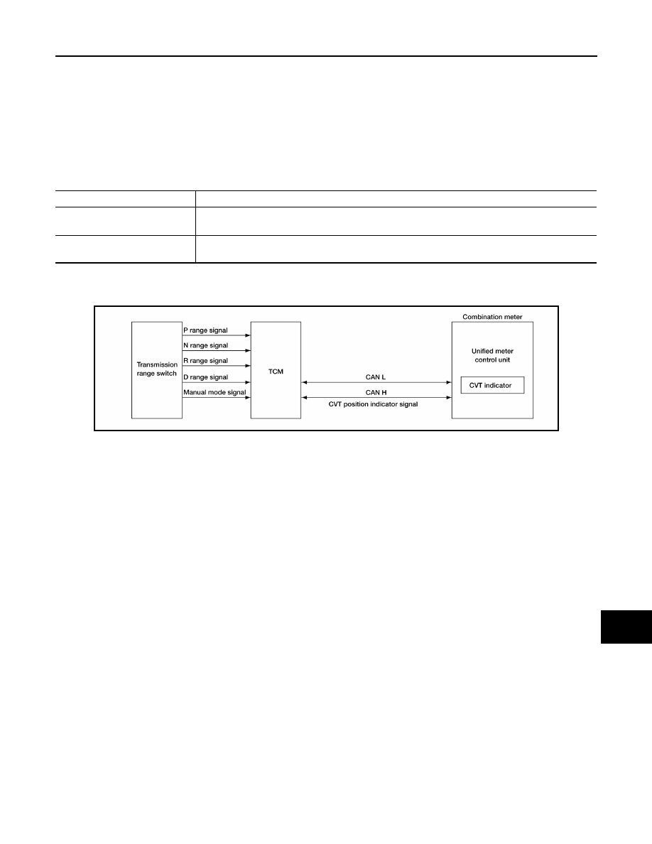
SHIFT POSITION INDICATOR : System Diagram

INFOID:0000000010049551

SHIFT POSITION INDICATOR : System Description

INFOID:0000000010049552

The TCM receives CVT indicator signals from the transmission range switch. The TCM then sends CVT posi-

tion indicator signals to the combination meter via CAN communication lines. The combination meter indicates

the received shift position.

4.

TCM F15

5.

BCM M18, M19, M20, M21 (view with 
instrument panel removed)

6.

ABS actuator and electric unit (control 
unit) E26

7.

Fuel level sensor unit and fuel pump 
(fuel level sensor) B42 (view with rear 
seat and inspection hole cover re-
moved)
⇐: Front

8.

Oil pressure switch F41 (view with en-
gine removed)

9.

Parking brake switch E35 (view with in-
strument lower cover LH removed)

Unit

Description

Combination meter

Indicates the vehicle speed according to the vehicle speed signal received from ABS actuator and 
electric unit (control unit) via CAN communication.

ABS actuator and electric unit 
(control unit)

Transmits the vehicle speed signal to the combination meter with CAN communication line.

AWNIA2703GB

MWI-20

< SYSTEM DESCRIPTION >

METER SYSTEM

SHIFT POSITION INDICATOR : Component Parts Location

INFOID:0000000010049553

1.

Combination meter M23, M24

2.

IPDM E/R E17, E18, E201, F10

3.

ECM E10

AWNIA2477GB

MWI

METER SYSTEM

MWI-21

< SYSTEM DESCRIPTION >

C

D

E

F

G

H

I

J

K

L

M

B

A

O

P

SHIFT POSITION INDICATOR : Component Description

INFOID:0000000010049554

WARNING LAMPS/INDICATOR LAMPS
WARNING LAMPS/INDICATOR LAMPS : System Diagram

INFOID:0000000010049555

WARNING LAMPS/INDICATOR LAMPS : System Description

INFOID:0000000010049556

OIL PRESSURE WARNING LAMP

The oil pressure warning lamp is controlled by the IPDM E/R (intelligent power distribution module engine

room).

Low oil pressure causes the oil pressure switch to provide a ground signal to the IPDM E/R. The IPDM E/R

then signals the combination meter (unified meter control unit) via the CAN communication lines and ground is

provided to the oil pressure warning lamp.

When power and ground are supplied, the oil pressure warning lamp illuminates.

4.

TCM F15

5.

BCM M18, M19, M20, M21 (view with 
instrument panel removed)

6.

ABS actuator and electric unit (control 
unit) E26

7.

Fuel level sensor unit and fuel pump 
(fuel level sensor) B42 (view with rear 
seat and inspection hole cover re-
moved)
⇐: Front

8.

Oil pressure switch F41 (view with en-
gine removed)

9.

Parking brake switch E35 (view with in-
strument lower cover LH removed)

Unit

Description

Combination meter

Displays the shift position using shift position signal received from TCM.

TCM

Transmits the shift position signal to the combination meter via CAN communication. 

AWNIA0009GB

MWI-22

< SYSTEM DESCRIPTION >

METER SYSTEM

WARNING LAMPS/INDICATOR LAMPS : Component Parts Location

INFOID:0000000010049557

1.

Combination meter M23, M24

2.

IPDM E/R E17, E18, E201, F10

3.

ECM E10

AWNIA2477GB


Content   ..  849  850  851  852   ..