Nissan Maxima. Manual - part 616
EXL-206
< DTC/CIRCUIT DIAGNOSIS >
[HALOGEN TYPE]
HEADLAMP (LO) CIRCUIT
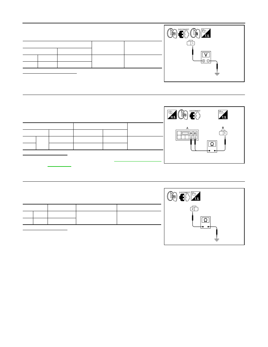
5. With EXTERNAL LAMPS ON, check the voltage between the
combination lamp connector and ground.
Is battery voltage present?
YES
>> GO TO 4.
NO
>> GO TO 3.
3.
CHECK HEADLAMP (LO) CIRCUIT FOR OPEN
1. Turn the ignition switch OFF.
2. Disconnect IPDM E/R connector E200.
3. Check continuity between the IPDM E/R harness connector (A)
and the front combination lamp harness connector (B).
Does continuity exist?
YES
>> Replace the IPDM E/R. Refer to
NO
>> Repair the harnesses or connectors.
4.
CHECK FRONT COMBINATION LAMP (LO) GROUND CIRCUIT
1. Disconnect the front combination lamp connector.
2. Check continuity between the front combination lamp harness
connector terminal and ground.
Does continuity exist?
YES
>> Inspect the headlamp bulb.
NO
>> Repair the harness.
(+)
(
−)
Voltage
Connector
Terminal
RH
E223
1
Ground
Battery voltage
LH
E212
1
AWLIA1663ZZ
A
B
Continuity
Connector
Terminal
Connector
Terminal
RH
E200
83
E223
1
Yes
LH
84
E212
1
AWLIA1664ZZ
Connector
Terminal
—
Continuity
RH
E223
2
Ground
Yes
LH
E212
2
AWLIA1665ZZ