Nissan Maxima. Manual - part 617
EXL-210
< DTC/CIRCUIT DIAGNOSIS >
[HALOGEN TYPE]
PARKING LAMP CIRCUIT
5. With EXTERNAL LAMPS ON, check the voltage between the
front combination lamp connector and ground.
6. With EXTERNAL LAMPS ON, check the voltage between the
rear combination lamp connector and ground.
7. With EXTERNAL LAMPS ON, check the voltage between the
license plate lamp connector and ground.
Is battery voltage present?
YES
>> GO TO 4.
NO
>> GO TO 3.
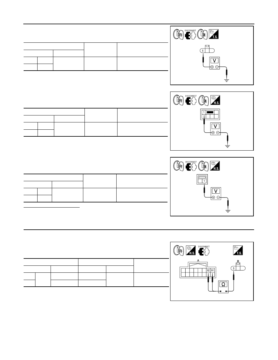
3.
CHECK PARKING LAMP CIRCUIT (OPEN)
1. Turn the ignition switch OFF.
2. Disconnect IPDM E/R connector E201.
3. Check continuity between the IPDM E/R harness connector (A)
and the front combination lamp harness connector (B).
(+)
(
−)
Voltage
Connector
Terminal
LH
E217
5
Ground
Battery voltage
RH
E224
AWLIA1644ZZ
(+)
(
−)
Voltage
Connector
Terminal
LH
B30
1
Ground
Battery voltage
RH
B45
AWLIA1645ZZ
(+)
(
−)
Voltage
Connector
Terminal
LH
T6
1
Ground
Battery voltage
RH
T8
AWLIA1646ZZ
A
B
Continuity
Connector
Terminal
Connector
Terminal
LH
E201
92
E217
5
Yes
RH
91
E224
AWLIA1647ZZ