Nissan Maxima. Manual - part 615


  Index      Nissan     Nissan Maxima (2009-2014 year) - Service and Repair Manual


Search            


Content   ..  613  614  615  616   ..


Nissan Maxima. Manual - part 615


EXL-202

< DTC/CIRCUIT DIAGNOSIS >

[HALOGEN TYPE]

HEADLAMP (HI) CIRCUIT

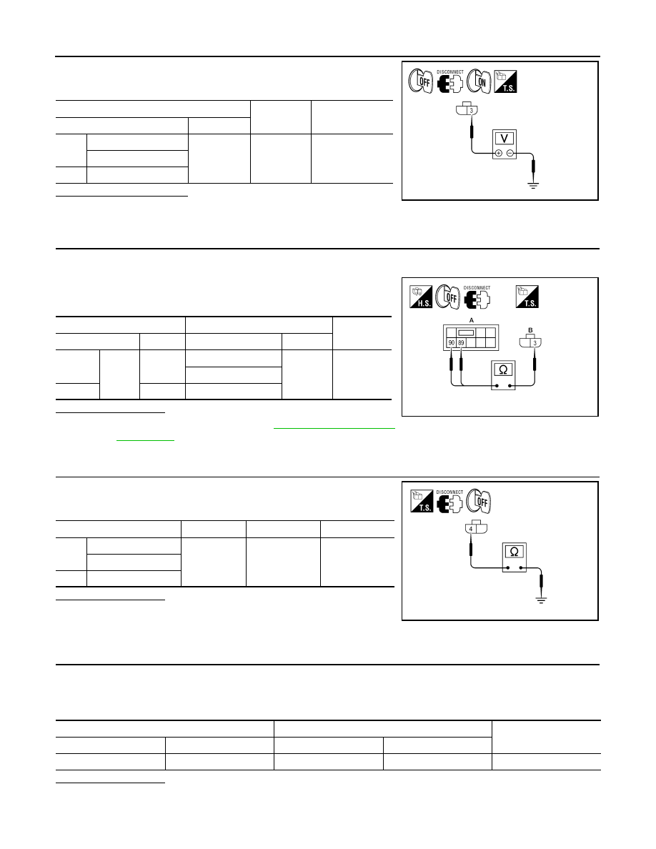
5. With EXTERNAL LAMP ON, check the voltage between the

combination lamp connector and ground.

Is battery voltage present?

YES

>> GO TO 4.

NO

>> GO TO 3.

3.

CHECK HEADLAMP (HI) CIRCUIT FOR OPEN

1. Turn the ignition switch OFF.

2. Disconnect IPDM E/R connector E200.

3. Check continuity between the IPDM E/R harness connector (A)

and the front combination lamp harness connector (B).

Does continuity exist?

YES

>> Replace IPDM E/R. Refer to 

PCS-35, "Removal and

Installation"

.

NO

>> Repair the harnesses or connectors.

4.

CHECK FRONT COMBINATION LAMP (HI) GROUND CIRCUIT

Check continuity between the front combination lamp harness con-

nector terminal and ground.

Does continuity exist?

YES

>> Inspect the headlamp bulb.

NO (Except RH with DTRL)>>Repair the harness.

NO (RH with DTRL)>>GO TO 5.

5.

CHECK CONTINUITY BETWEEN FRONT COMBINATION LAMP RH (HI) AND DAYTIME LIGHT RELAY

1. Disconnect daytime light relay connector.

2. Check continuity between front combination lamp RH harness connector and daytime light relay harness

connector.

Does continuity exist?

YES

>> GO TO 6.

NO

>> Repair the harness or connector.

(+)

(

−)

Voltage

Connector

Terminal

RH

E222 (without DTRL)

3

Ground

Battery voltage

E233 (with DTRL)

LH

E213 

AWLIA1641ZZ

A

B

Continuity

Connector

Terminal

Connector

Terminal

RH

E200

89

E222 (without DTRL)

3

Yes

E233 (with DTRL)

LH

90

E213 

AWLIA1642ZZ

Connector

Terminal

Continuity

RH

E222 (without DTRL)

4

Ground

Yes

E233 (with DTRL)

LH

E213 

AWLIA1643ZZ

Front combination lamp RH

Daytime light relay

Continuity

Connector

Terminal

Connector

Terminal

E233

4

E228

3

Yes

HEADLAMP (HI) CIRCUIT

EXL-203

< DTC/CIRCUIT DIAGNOSIS >

[HALOGEN TYPE]

C

D

E

F

G

H

I

J

K

M

A

B

EXL

N

O

P

6.

CHECK DAYTIME LIGHT RELAY GROUND CIRCUIT

Check continuity between daytime light relay harness connector and ground.

Does continuity exist?

YES

>> GO TO 7.

NO

>> Repair the harness or connector.

7.

CHECK DAYTIME LIGHT RELAY FUSE

1. Turn the ignition switch OFF.

2. Check that the following fuse is not open.

Is the fuse open?

YES

>> Replace the fuse after repairing the affected circuit.

NO

>> GO TO 8.

8.

CHECK DAYTIME LIGHT RELAY CIRCUIT FOR OPEN

1. Disconnect IPDM E/R connector E18 and E201.

2. Check continuity between the IPDM E/R harness connector and the daytime light relay harness connec-

tor.

Does continuity exist?

YES

>> GO TO 9

NO

>> Repair the harnesses or connectors.

9.

CHECK DAYTIME LIGHT RELAY

Check daytime light relay. Refer to 

EXL-203, "Component Inspection"

.

Is the inspection result normal?

YES

>> Replace IPDM E/R. Refer to 

PCS-35, "Removal and Installation"

.

NO

>> Replace daytime light relay.

Component Inspection

INFOID:0000000010051060

1.

 CHECK DAYTIME LIGHT RELAY

1. Turn ignition switch OFF.

2. Remove daytime light relay.

3. Check the continuity between daytime light relay terminals under the following conditions.

Daytime light relay

Ground

Continuity

Connector

Terminal

E228

4

Yes

Unit

Location

Fuse No.

Capacity

Daytime light relay

IPDM E/R

54

10A

IPDM E/R

Daytime light relay

Continuity

Connector

Terminal

Connector

Terminal

E18

6

E228

1

Yes

5

E201

105

2

Terminals

Condition

Continuity

3 and 5

12V direct current supply between terminals 1 and 2

Yes

No current supply

No

EXL-204

< DTC/CIRCUIT DIAGNOSIS >

[HALOGEN TYPE]

HEADLAMP (HI) CIRCUIT

Is the inspection result normal?

YES

>> Inspection End.

NO

>> Replace daytime light relay

3 and 4

12V direct current supply between terminals 1 and 2

No

No current supply

Yes

Terminals

Condition

Continuity

HEADLAMP (LO) CIRCUIT

EXL-205

< DTC/CIRCUIT DIAGNOSIS >

[HALOGEN TYPE]

C

D

E

F

G

H

I

J

K

M

A

B

EXL

N

O

P

HEADLAMP (LO) CIRCUIT

Description

INFOID:0000000010051061

The IPDM E/R (intelligent power distribution module engine room) controls the headlamp low relay based on

inputs from the BCM over the CAN communication lines. When the headlamp low relay is energized, power

flows through fuses 51 and 52, located in the IPDM E/R. Power then flows to the front combination lamps to

the headlamp low beam.

Component Function Check

INFOID:0000000010051062

1.

CHECK HEADLAMP (LO) OPERATION

WITHOUT CONSULT

1. Start IPDM E/R auto active test. Refer to 

PCS-11, "Diagnosis Description"

.

2. Check that the headlamp is turned ON.

NOTE:

HI/LO is repeated 1 second each when using the IPDM E/R auto active test.

CONSULT

1. Select "EXTERNAL LAMPS" of IPDM E/R active test item.

2. While operating the test item, check that the headlamp is turned ON.

Is the headlamp turned ON?

YES

>> Headlamp (LO) is normal.

NO

>> Refer to 

EXL-205, "Diagnosis Procedure"

.

Diagnosis Procedure

INFOID:0000000010051063

Regarding Wiring Diagram information, refer to 

EXL-257, "Wiring Diagram"

.

1.

CHECK HEADLAMP (LO) FUSES

1. Turn the ignition switch OFF.

2. Check that the following fuses are not open.

Is the fuse open?

YES

>> Repair the harness and replace the fuse.

NO

>> GO TO 2.

2.

CHECK HEADLAMP (LO) OUTPUT VOLTAGE

CONSULT

1. Turn the ignition switch OFF.

2. Disconnect the front combination lamp connector.

3. Turn the ignition switch ON.

4. Select "EXTERNAL LAMPS" of IPDM E/R active test item.

LO

: Headlamp ON

OFF

: Headlamp OFF

Unit

Location

Fuse No.

Capacity

Headlamp LO (LH) IPDM E/R

51

15A

Headlamp LO (RH) 

IPDM E/R

52

15A


Content   ..  613  614  615  616   ..