Nissan Maxima. Manual - part 404
EC-100
< SYSTEM DESCRIPTION >
[VQ35DE]
EVAPORATIVE EMISSION SYSTEM
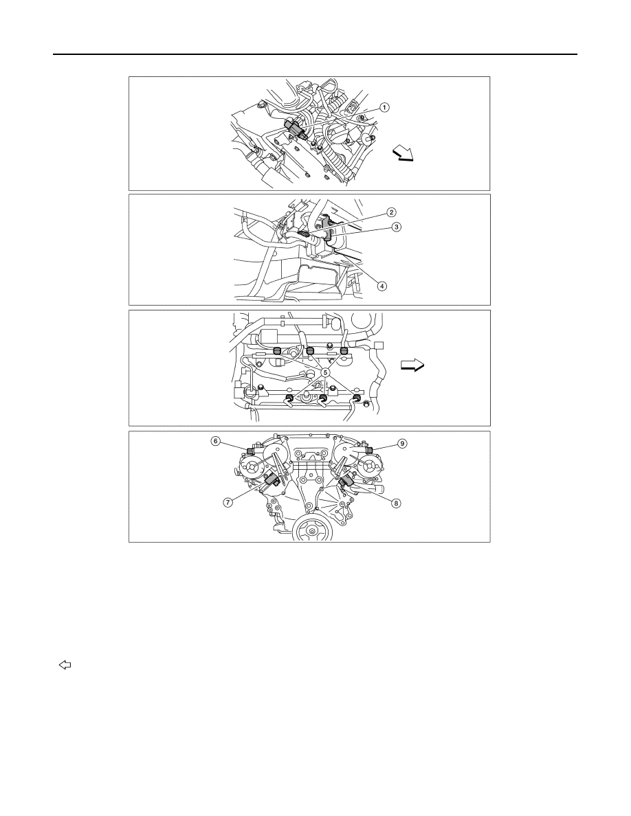
1.
Electronic controlled engine mount
control solenoid valve (view with en-
gine cover removed)
2.
EVAP control system pressure sensor
(view with rear suspension member re-
moved)
3.
EVAP canister vent control valve
4.
EVAP canister
5.
Fuel injector harness connector (view
with intake manifold collector removed)
6.
Exhaust valve timing control magnet
retarder (bank 1) (view with engine re-
moved)
7.
Intake valve timing control solenoid
valve (bank 1)
8.
Intake valve timing control solenoid
valve (bank 2)
9.
Exhaust valve timing control magnet
retarder (bank 2)
: Vehicle front
ALBIA0606ZZ