Nissan Maxima. Manual - part 402
EC-92
< SYSTEM DESCRIPTION >
[VQ35DE]
ELECTRONIC CONTROLLED ENGINE MOUNT
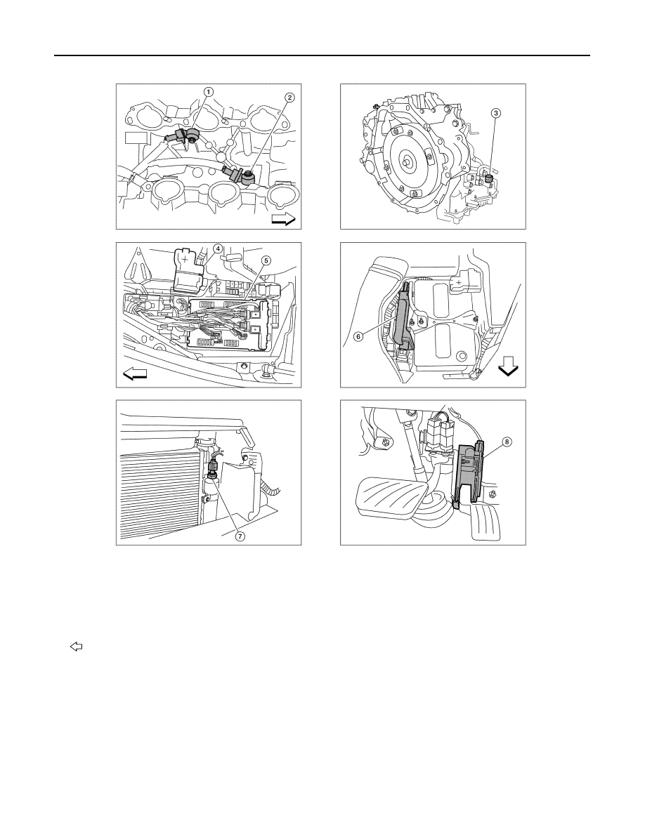
1.
Knock sensor (bank 2) (view with in-
take manifold removed)
2.
Knock sensor (bank 1)
3.
Transmission range switch
(view with CVT removed)
4.
Battery
5.
IPDM E/R
6.
ECM
7.
Refrigerant pressure sensor (view
with front grille removed)
8.
Accelerator pedal position sensor
: Vehicle front
ALBIA0607ZZ