Nissan Maxima. Manual - part 343
DOOR REQUEST SWITCH
DLK-91
< DTC/CIRCUIT DIAGNOSIS >
C
D
E
F
G
H
I
J
L
M
A
B
DLK
N
O
P
DOOR REQUEST SWITCH
Description
INFOID:0000000009471673
Transmits door lock/unlock operation to BCM.
Component Function Check
INFOID:0000000009471674
1.
CHECK FUNCTION
With CONSULT
Check door request switch REQ SW-DR, REQ SW-AS in Data Monitor mode.
Is the inspection result normal?
YES
>> Door request switch is OK.
NO
>> Refer to
.
Diagnosis Procedure
INFOID:0000000009471675
Regarding Wiring Diagram information, refer to
.
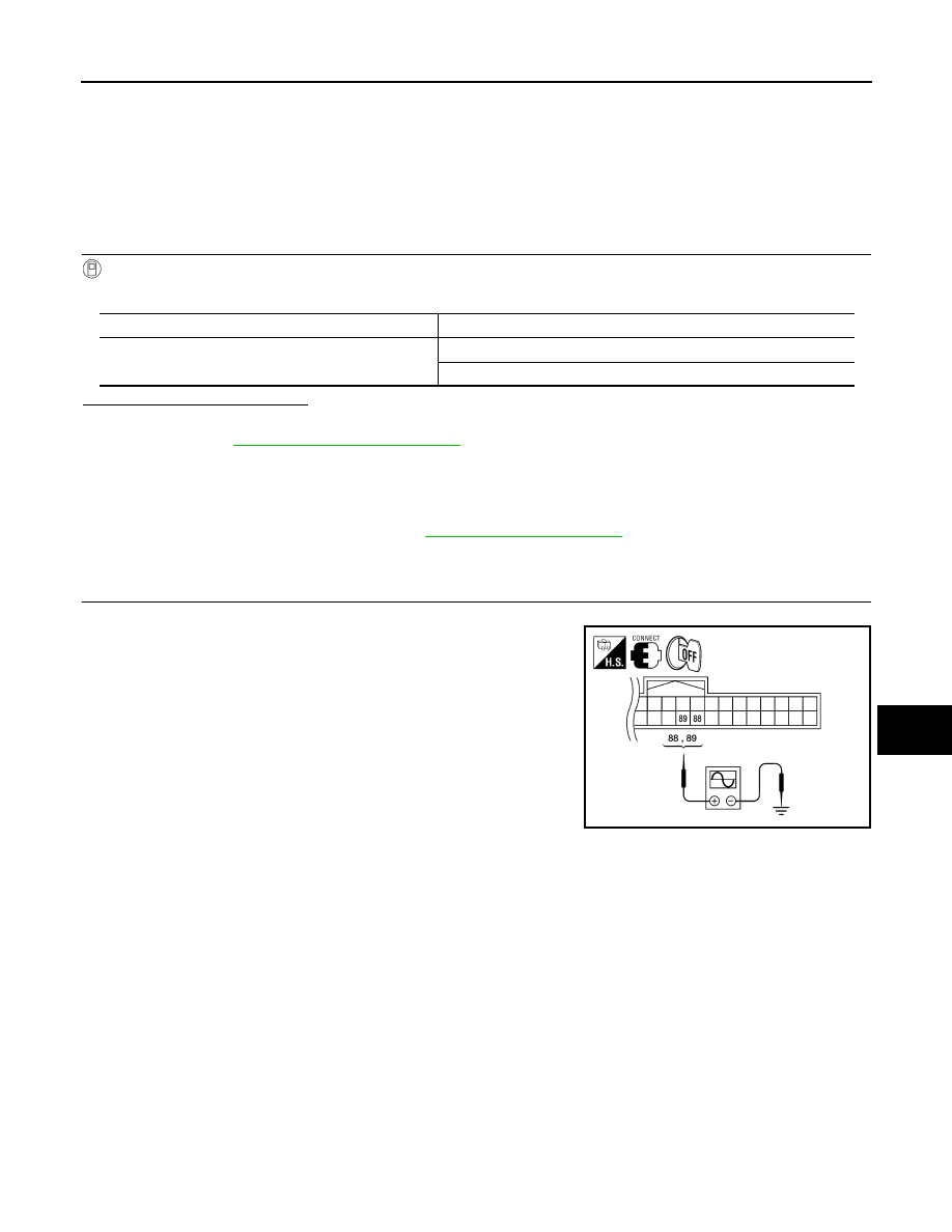
1.
CHECK DOOR REQUEST SWITCH OUTPUT SIGNAL
1. Turn ignition switch OFF.
2. Check voltage between BCM harness connector and ground.
Monitor item
Condition
REQ SW-DR
REQ SW-AS
Door request switch is pressed : ON
Door request switch is released : OFF
ALKIA0376ZZ