Nissan Maxima. Manual - part 344


  Index      Nissan     Nissan Maxima (2009-2014 year) - Service and Repair Manual


Search            


Content   ..  342  343  344  345   ..


Nissan Maxima. Manual - part 344


TRUNK OPENER REQUEST SWITCH

DLK-95

< DTC/CIRCUIT DIAGNOSIS >

C

D

E

F

G

H

I

J

L

M

A

B

DLK

N

O

P

Is the inspection result normal?

YES

>> GO TO 3

NO

>> Repair or replace harness between BCM and trunk opener request switch.

3.

CHECK TRUNK OPENER REQUEST SWITCH GROUND CIRCUIT

Check continuity between trunk opener request switch connector and ground.

Is the inspection result normal?

YES

>> GO TO 4

NO

>> Repair or replace trunk opener request switch ground circuit.

4.

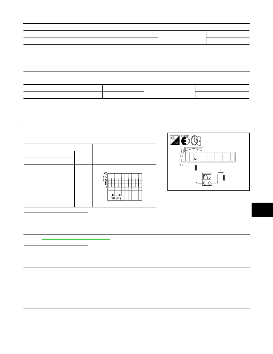
CHECK BCM OUTPUT SIGNAL

1. Connect BCM connector.

2. Check voltage between BCM connector and ground.

Is the inspection result normal?

YES

>> GO TO 5

NO

>> Replace BCM. Refer to 

BCS-79, "Removal and Installation"

.

5.

CHECK TRUNK OPENER REQUEST SWITCH

Refer to 

DLK-95, "Component Inspection"

.

Is the inspection result normal?

YES

>> GO TO 6

NO

>> Replace trunk opener request switch. 

6.

CHECK INTERMITTENT INCIDENT

Refer to 

GI-41, "Intermittent Incident"

.

>> Inspection End.

Component Inspection

INFOID:0000000009471680

1.

CHECK TRUNK OPENER REQUEST SWITCH

Check trunk opener request switch.

BCM connector

Terminal

Ground

Continuity 

M21

141

No

Trunk opener request switch connector

Terminal

Ground

Continuity 

T5

2

Yes

Terminals

Voltage (V)

(Approx.)

(+)

(–)

BCM connector

Terminal

M21

141

Ground

ALKIA0397ZZ

JPMIA0016GB

DLK-96

< DTC/CIRCUIT DIAGNOSIS >

TRUNK OPENER REQUEST SWITCH

Is the inspection result normal?

YES

>> Inspection End.

NO

>> Replace trunk opener request switch. 

Terminal

Trunk opener request switch 

condition

Continuity 

Trunk opener request switch

1

2

Pressed

Yes

Released

No

DOOR LOCK ACTUATOR

DLK-97

< DTC/CIRCUIT DIAGNOSIS >

C

D

E

F

G

H

I

J

L

M

A

B

DLK

N

O

P

DOOR LOCK ACTUATOR

DRIVER SIDE
DRIVER SIDE : Description

INFOID:0000000009471681

Locks/unlocks the door with the signal from BCM.

DRIVER SIDE : Component Function Check

INFOID:0000000009471682

1.

CHECK FUNCTION

1. Use CONSULT to perform Active Test (“DOOR LOCK”).

2. Touch “ALL LOCK” or “ALL UNLOCK” to check that it works normally.
Is the inspection result normal?

YES

>> Door lock actuator is OK.

NO

>> Refer to 

DLK-97, "DRIVER SIDE : Diagnosis Procedure"

.

DRIVER SIDE : Diagnosis Procedure

INFOID:0000000009471683

Regarding Wiring Diagram information, refer to 

DLK-150, "Wiring Diagram"

.

1.

CHECK OUTPUT SIGNAL

Check voltage between BCM connector and ground.

Is the inspection result normal?

YES

>> GO TO 3

NO

>> GO TO 2

2.

CHECK DOOR LOCK ACTUATOR CIRCUIT

1. Turn ignition switch OFF.

2. Disconnect BCM and front door lock actuator driver side connector.

3. Check continuity between BCM connector and front door lock actuator driver side connector. 

4. Check continuity between BCM connector and ground.

Is the inspection result normal?

YES

>> Replace front door lock actuator LH.

NO

>> Repair or replace harness.

Terminals

Condition of door lock and 

unlock switch

Voltage (V)

(Approx.)

(+)

(–)

BCM

connector

Terminal

M17

8

Ground

Lock

→ Battery voltage → 0

9

Unlock

→ Battery voltage → 0

BCM connector

Terminal

Door lock actuator 

connector

Terminal

Continuity 

M17

8

D10

1

Yes

9

2

BCM connector

Terminal

Continuity 

M17

8

Ground

No

9

DLK-98

< DTC/CIRCUIT DIAGNOSIS >

DOOR LOCK ACTUATOR

3.

CHECK INTERMITTENT INCIDENT

Refer to 

GI-41, "Intermittent Incident"

.

>> Inspection End.

PASSENGER SIDE
PASSENGER SIDE : Description

INFOID:0000000009471684

Locks/unlocks the door with the signal from BCM.

PASSENGER SIDE : Component Function Check

INFOID:0000000009471685

1.

CHECK FUNCTION

1. Use CONSULT to perform Active Test (“DOOR LOCK”).

2. Touch “ALL LOCK” or “ALL UNLOCK” to check that it works normally.
Is the inspection result normal?

YES

>> Door lock actuator is OK.

NO

>> Refer to 

DLK-98, "PASSENGER SIDE : Diagnosis Procedure"

.

PASSENGER SIDE : Diagnosis Procedure

INFOID:0000000009471686

Regarding Wiring Diagram information, refer to 

DLK-150, "Wiring Diagram"

.

1.

CHECK DOOR LOCK ACTUATOR SIGNAL

Check voltage between BCM connector and ground.

Is the inspection result normal?

YES

>> GO TO 3

NO

>> GO TO 2

2.

CHECK DOOR LOCK ACTUATOR CIRCUIT

1. Turn ignition switch OFF. 

2. Disconnect BCM and front door lock actuator RH connectors. 

3. Check continuity between BCM connector and front door lock actuator RH. 

4. Check continuity between BCM connector and ground.

Terminals

Condition of door lock 

and unlock switch

Voltage (V)

(Approx.)

(+)

(–)

BCM

connector

Terminal

M17

8

Ground

Lock

→ Battery voltage → 0

5

Unlock

→ Battery voltage → 0

BCM connec-

tor

Terminal

Front door lock 

actuator RH 

connector

Terminal

Continuity 

M17

8

D108

5

Yes

5

6

BCM connector

Terminal

Continuity 

M17

8

Ground

No

5


Content   ..  342  343  344  345   ..