Nissan Maxima. Manual - part 338
DOOR LOCK AND UNLOCK SWITCH
DLK-71
< DTC/CIRCUIT DIAGNOSIS >
C
D
E
F
G
H
I
J
L
M
A
B
DLK
N
O
P
Is the inspection result normal?
YES
>> GO TO 4
NO
>> GO TO 2
2.
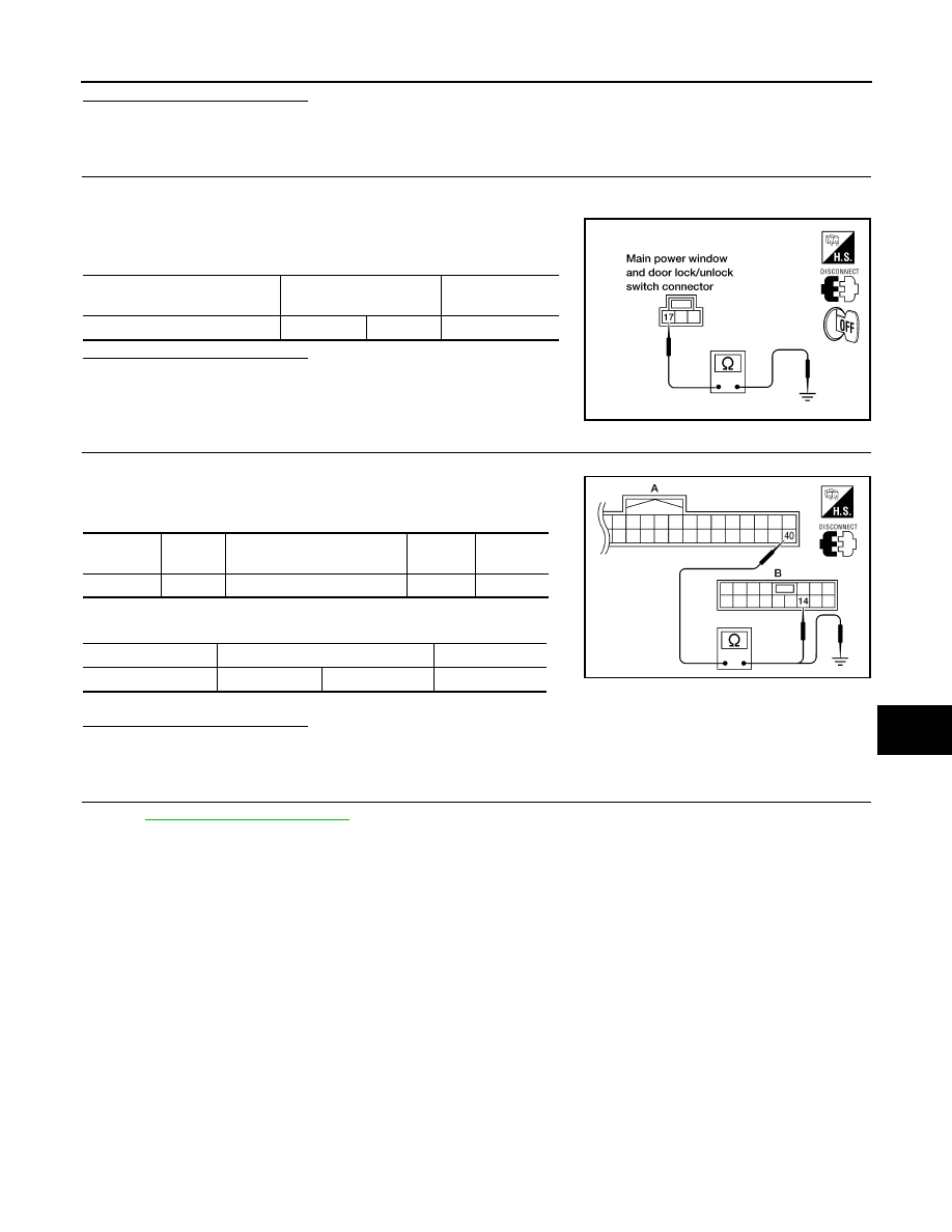
CHECK POWER WINDOW SWITCH GROUND
1. Turn ignition switch OFF.
2. Disconnect main power window and door lock/unlock switch connector.
3. Check continuity between main power window and door lock/
unlock switch connector and ground.
Is the inspection result normal?
YES
>> GO TO 3
NO
>> Repair or replace harness.
3.
CHECK POWER WINDOW SERIAL LINK CIRCUIT
1. Disconnect BCM connector.
2. Check continuity between BCM connector and main power win-
dow and door lock/unlock switch connector.
3. Check continuity between BCM connector and ground.
Is the inspection result normal?
YES
>> GO TO 4
NO
>> Repair or replace harness.
4.
CHECK INTERMITTENT INCIDENT
GI-41, "Intermittent Incident"
.
>> Inspection End.
DRIVER SIDE : Special Repair Requirement
INFOID:0000000009471643
INITIALIZATION PROCEDURE
1. Disconnect battery negative terminal or main power window and door lock/unlock switch. Reconnect it
after a minute or more.
2. Turn ignition switch ON.
3. Operate power window switch to fully open the window. (This operation is unnecessary if the window is
already fully open)
4. Continue pulling the power window switch UP (AUTO-UP operation). Even after glass stops at fully closed
position, keep pulling the switch for 4 seconds or more.
5. Inspect anti-pinch function.
CHECK ANTI-PINCH FUNCTION
1. Fully open the door window.
2. Place a piece of wood near fully closed position.
3. Close door glass completely with AUTO-UP.
Main power window and door
lock/unlock switch connector
Terminal
Continuity
D8
17
Ground
Yes
LIIA0392E
BCM
connector
Terminal
Main power window and door
lock/unlock switch connector
Terminal
Continuity
A: M18
40
B: D7
14
Yes
BCM connector
Terminals
Continuity
A: M18
40
Ground
No
ALKIA0334ZZ