Nissan Maxima. Manual - part 261


  Index      Nissan     Nissan Maxima (2009-2014 year) - Service and Repair Manual


Search            


Content   ..  259  260  261  262   ..


Nissan Maxima. Manual - part 261


C1155 BR FLUID LEVEL LOW

BRC-65

< DTC/CIRCUIT DIAGNOSIS >

[VDC/TCS/ABS]

C

D

E

G

H

I

J

K

L

M

A

B

BRC

N

O

P

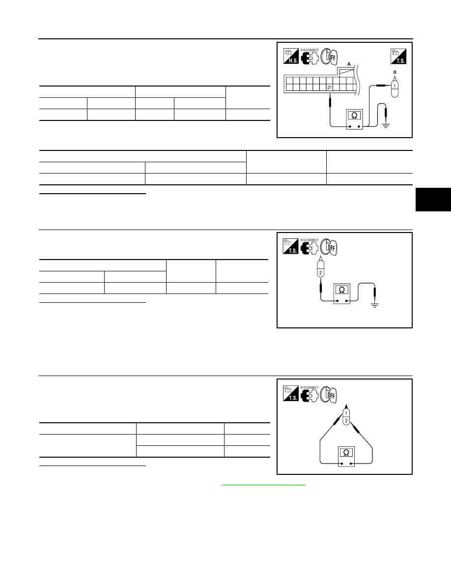
1. Disconnect combination meter connector.

2. Check continuity between combination meter connector M24 (A)

terminal 27 and brake fluid level switch connector E24 (B) termi-

nal 1.

3. Check continuity between combination meter connector M24 (A)

terminal 27 and ground.

Is the inspection result normal?

YES

>> GO TO 4

NO

>> Repair or replace malfunctioning components.

4.

CHECK BRAKE FLUID LEVEL SWITCH GROUND CIRCUIT

Check continuity between brake fluid level switch connector E24 ter-

minal 2 and ground.

Is the inspection result normal?

YES

>> Inspection End.

NO

>> • Repair or replace malfunctioning components.

• Perform the self-diagnosis, and make sure that the

result shows 

″NO DTC IS DETECTED″.

Component Inspection

INFOID:0000000010049114

1.

CHECK BRAKE FLUID LEVEL SWITCH

1. Turn ignition switch OFF.

2. Disconnect brake fluid level switch connector.

3. Check continuity between brake fluid level switch terminals 1

and 2.

Is the inspection result normal?

YES

>> Inspection End.

NO

>> Replace brake fluid level switch. Refer to 

BR-24, "Exploded View"

.

Combination meter 

Brake fluid level switch

Continuity

Connector

Terminal

Connector

Terminal

M24 (A)

27

E24 (B)

1

Yes

Combination meter 

Ground

Continuity

Connector

Terminal

M24 (A)

27

No

AWFIA0451ZZ

Brake fluid level switch

Ground

Continuity

Connector

Terminal

 E24

2

Yes

ALFIA0028ZZ

Brake fluid level switch terminals

Condition

Continuity

1— 2

Brake fluid reservoir full

No

Brake fluid reservoir empty

Yes

ALFIA0026ZZ

BRC-66

< DTC/CIRCUIT DIAGNOSIS >

[VDC/TCS/ABS]

C1156 ST ANG SEN COM CIR

C1156 ST ANG SEN COM CIR

Description

INFOID:0000000010049115

The steering angle sensor is connected to the ABS actuator and electric unit (control unit) in addition to CAN

lines. CAN (Controller Area Network) is a serial communication line for real time application. It is an on-vehicle

multiplex communication line with high data communication speed and excellent error detection ability. Many

electronic control units are equipped onto a vehicle, and each control unit shares information and links with

other control units during operation (not independent). In CAN communication, control units are connected

with 2 communication lines (CAN H line, CAN L line) allowing a high rate of information transmission with less

wiring. Each control unit transmits/receives data but selectively reads required data only.

DTC Logic

INFOID:0000000010049116

DTC DETECTION LOGIC

DTC CONFIRMATION PROCEDURE

1.

CHECK SELF-DIAGNOSIS RESULTS

Check the self-diagnosis results.

Is above displayed on the self-diagnosis display?

YES

>> Proceed to diagnosis procedure. Refer to 

BRC-66, "Diagnosis Procedure"

.

NO

>> Inspection End.

Diagnosis Procedure

INFOID:0000000010049117

1.

CONNECTOR INSPECTION

1. Turn ignition switch OFF.

2. Disconnect ABS actuator and electric unit (control unit) connector.

3. Check terminals for deformation, disconnection, looseness, and so on. If any malfunction is found, repair

or replace terminals.

4. Reconnect connector and perform self-diagnosis. Refer to 

BRC-21, "CONSULT Function (ABS)"

.

Is above displayed on the self-diagnosis display?

YES

>> Refer to 

LAN-15, "Trouble Diagnosis Flow Chart"

.

NO

>> Inspection End.

DTC

Display item

Malfunction detected condition

Possible cause

C1156

ST ANG SEN COM CIR

When steering angle sensor is not transmitting CAN 
communication signal to the ABS actuator and electric 
unit (control unit).

• Harness or connector
• CAN communication line
• Steering angle sensor
• ABS actuator and electric unit 

(control unit)

Self-diagnosis results

ST ANG SEN COM CIR

Self-diagnosis results

CAN COMM CIRCUIT

ST ANG SEN COM CIR

U1000 CAN COMM CIRCUIT

BRC-67

< DTC/CIRCUIT DIAGNOSIS >

[VDC/TCS/ABS]

C

D

E

G

H

I

J

K

L

M

A

B

BRC

N

O

P

U1000 CAN COMM CIRCUIT

Description

INFOID:0000000010049118

CAN (Controller Area Network) is a serial communication line for real time application. It is an on-vehicle mul-

tiplex communication line with high data communication speed and excellent error detection ability. Many elec-

tronic control units are equipped onto a vehicle, and each control unit shares information and links with other

control units during operation (not independent). In CAN communication, control units are connected with 2

communication lines (CAN H line, CAN L line) allowing a high rate of information transmission with less wiring.

Each control unit transmits/receives data but selectively reads required data only.

DTC Logic

INFOID:0000000010049119

DTC DETECTION LOGIC

Diagnosis Procedure

INFOID:0000000010049120

1.

CHECK CONNECTOR

1. Turn ignition switch OFF.

2. Disconnect ABS actuator and electric unit (control unit) connector.

3. Check terminals for deformation, disconnection, looseness, and so on. If any malfunction is found, repair

or replace terminals.

4. Reconnect connector and perform self-diagnosis. Refer to 

BRC-21, "CONSULT Function (ABS)"

.

Is above displayed on the self-diagnosis display?

YES

>> Refer to 

LAN-15, "Trouble Diagnosis Flow Chart"

.

NO

>> Inspection End.

DTC

Display item

Malfunction detected condition

Possible cause

U1000

CAN COMM CIRCUIT

When ABS actuator and electric unit (control unit) is not 
transmitting or receiving CAN communication signal for 2 
seconds or more.

• CAN communication line
• ABS actuator and electric unit 

(control unit)

Self-diagnosis results

CAN COMM CIRCUIT

BRC-68

< DTC/CIRCUIT DIAGNOSIS >

[VDC/TCS/ABS]

PARKING BRAKE SWITCH

PARKING BRAKE SWITCH

Description

INFOID:0000000010049121

The parking brake switch converts the status of the parking brake pedal to an electric signal and transmits it to

the combination meter. The combination meter, through CAN communication, transmits the signal to the ABS

actuator and electric unit (control unit).

Component Function Check

INFOID:0000000010049122

1.

CHECK PARKING BRAKE SWITCH OPERATION

Operate the parking brake and check that the brake warning lamp in the combination meter turns on/off cor-

rectly.

Is the inspection result normal?

YES

>> Inspection End.

NO

>> Go to diagnosis procedure. Refer to 

BRC-68, "Diagnosis Procedure"

.

Diagnosis Procedure

INFOID:0000000010049123

Regarding Wiring Diagram information, refer to 

BRC-83, "Wiring Diagram"

.

1.

CHECK PARKING BRAKE SWITCH CIRCUIT

1. Disconnect combination meter connector and parking brake

switch connector. 

2. Check continuity between combination meter connector M24 (A)

terminal 26 and parking brake switch connector E35 (B) terminal

1.

3. Check continuity between combination meter harness connector

M24 (A) terminal 26 and ground.

Is the inspection result normal?

YES

>> GO TO 2

NO

>> Repair harness or connector.

2.

CHECK PARKING BRAKE SWITCH

Perform parking brake switch component inspection. Refer to 

BRC-69, "Component Inspection"

.

Is the inspection result normal?

YES

>> Check parking brake switch case ground condition.

NO

>> Replace parking brake switch.

Condition

Brake warning lamp illumination

Parking brake engaged

ON

Parking brake not engaged

OFF

Combination meter 

Parking brake switch

Continuity

Connector

Terminal

Connector

Terminal

M24 (A)

26

E35 (B)

1

Yes

AWFIA0452ZZ

Combination meter 

Ground

Continuity

Connector

Terminal

M24 (A)

26

No


Content   ..  259  260  261  262   ..