Nissan Maxima. Manual - part 262
PARKING BRAKE SWITCH
BRC-69
< DTC/CIRCUIT DIAGNOSIS >
[VDC/TCS/ABS]
C
D
E
G
H
I
J
K
L
M
A
B
BRC
N
O
P
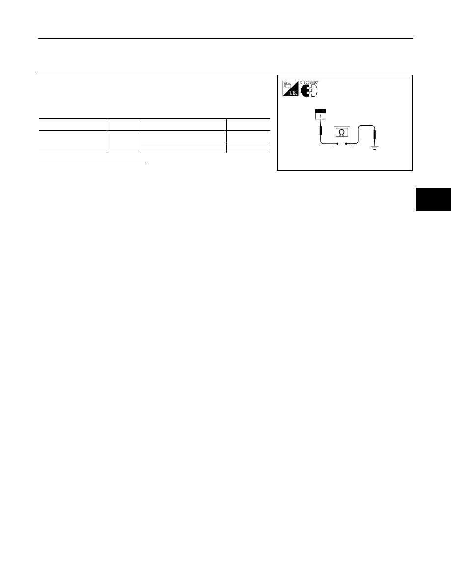
Component Inspection
INFOID:0000000010049124
1.
CHECK PARKING BRAKE SWITCH
1. Turn ignition switch OFF.
2. Disconnect parking brake switch connector.
3. Check continuity between parking brake switch terminal 1 and
ground.
Is the inspection result normal?
YES
>> Inspection End.
NO
>> Replace parking brake switch.
Component
Terminal
Condition
Continuity
Parking brake switch
1
Parking brake depressed
Yes
Parking brake released
No
AWNIA0018ZZ