Nissan Maxima. Manual - part 1179


  Index      Nissan     Nissan Maxima (2009-2014 year) - Service and Repair Manual


Search            


Content   ..  1177  1178  1179  1180   ..


Nissan Maxima. Manual - part 1179


TM-180

< REMOVAL AND INSTALLATION >

[CVT: RE0F09B]

CONTROL VALVE

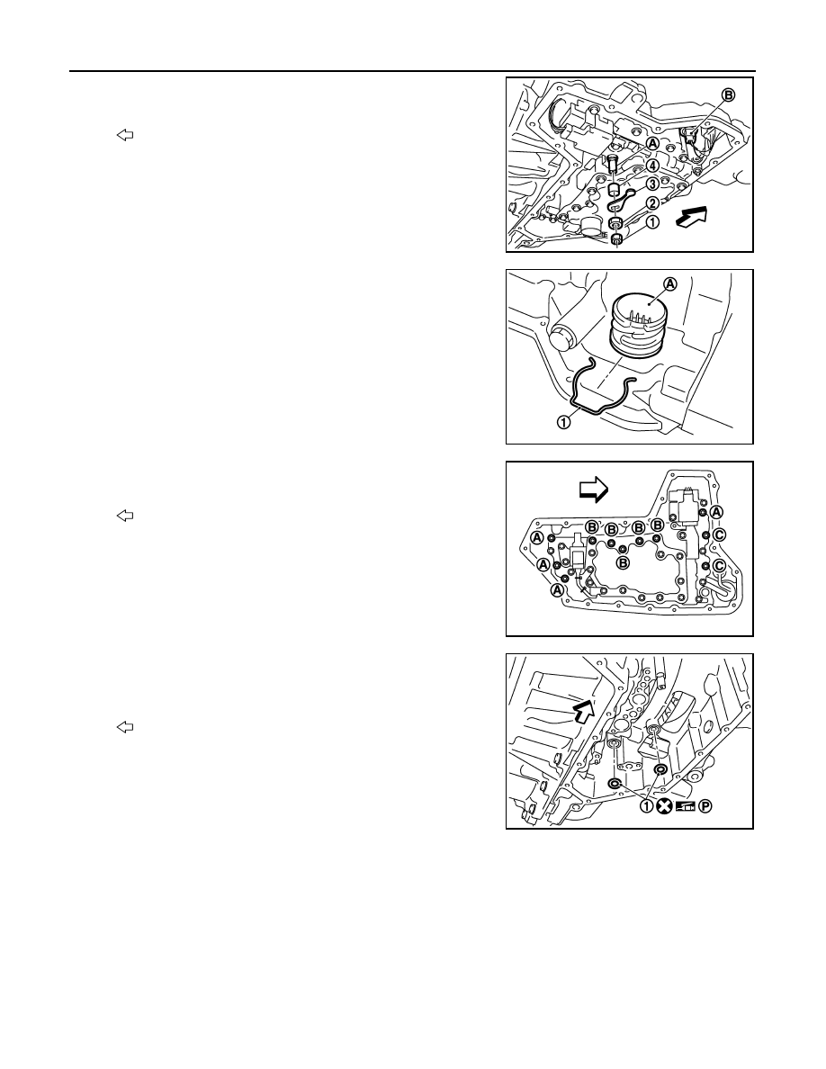
6. Remove the lock nut (1) and (2), and then remove manual plate

(3).

7. Remove the collar (4) from the manual shaft (A).

CAUTION:

Do not drop the collar.

8. Disconnect the primary pressure sensor harness connector (B).

9. Remove the snap ring (1) from the CVT unit harness connector

(A).

10. Press the CVT unit harness connector (A) into the transaxle

case.

CAUTION:

Do not damage the CVT unit harness connector.

NOTE:

Clean around the CVT unit harness connector to prevent foreign

materials from entering into the transaxle case.

11. Remove the control valve bolts (A), (B) and (C), and then

remove the control valve from the transaxle case.

CAUTION:

• Do not drop the control valve, ratio control valve and

manual shaft.

• Confirm position of the shift link for ease of installation.

12. Remove the lip seal (1) from the transaxle case.

CAUTION:

Do not reuse lip seal.

INSTALLATION

: Front

SCIA8137J

SCIA8138J

: Front

SCIA8139J

: Front

SCIA8140J

CONTROL VALVE

TM-181

< REMOVAL AND INSTALLATION >

[CVT: RE0F09B]

C

E

F

G

H

I

J

K

L

M

A

B

TM

N

O

P

1. Install the lip seal (1) to the transaxle case.

CAUTION:

Do not reuse lip seal.

2. Check the harness connector (B), O-ring (C), and the orientation

of shift link (A) on the control valve.

CAUTION:

• Do not touch or wipe out the control valve mating surface.

• Be careful not to drop the ratio control valve (D), because

the return spring in ratio control valve may push out the

ratio control valve.

• Be sure shift link (A) is in the proper position prior to

installation.

• Do not reuse O-ring.

• Be sure to apply CVT fluid to O-ring (C).

• Check that a notch (E) of shift link engages with the step

motor and that a bracket of shift link engages with a hole

(F) of step motor.

• Place the harness connector on the secondary pressure

sensor (G).

3. Temporarily tighten the control valve with 2 control valve bolts,

while adjusting the shift link (A) to engage the notch (C) of shift

link with the pin (B) of pulley sensor.

CAUTION:

• Do not pinch the harness into between the control valve

and the transaxle case.

• Do not damage the control valve while installing.

• Check that the notch (C) at one end of shift link (A)

engages with the pin (B) of pulley sensor. Check that the

notch (D) at the other end of shift link (A) engages with

step motor and that the bracket of shift link (A) engages

with the hole (E) of step motor.

: Front

SCIA8140J

SCIA8222J

SCIA8223J

TM-182

< REMOVAL AND INSTALLATION >

[CVT: RE0F09B]

CONTROL VALVE

4. Install the control valve bolts (A), (B), and (C).

5. Install the collar (1) to the manual shaft (A).

6. Install the manual plate (1) while aligning with the groove (A) of

the manual valve.

7. Install the lock-nut (2), and then the lock-nut (3).

8. Install the CVT unit harness connector (A) to the transaxle case.

CAUTION:

Engage the notch (B) of CVT unit harness connector with

the protrusion (C) of transaxle case.

9. Install the primary pressure sensor harness connector (D)

10. Install the snap ring (1) to the CVT unit harness connector (A).
11. Install the magnet while aligning it with the convex side of oil

pan.

CAUTION:

Completely eliminate the iron powder from the magnet area

of oil pan and the magnet.

: Front

Bolt

Bolt length (mm)

Number of bolts

A

30

4

B

70

5

C

53

2

SCIA8139J

: Front

SCIA8141J

: Front

SCIA8218J

: Front

SCIA8221J

SCIA8138J

CONTROL VALVE

TM-183

< REMOVAL AND INSTALLATION >

[CVT: RE0F09B]

C

E

F

G

H

I

J

K

L

M

A

B

TM

N

O

P

12. Install the oil pan. Refer to 

TM-177, "Removal and Installation"

.

13. Connect the CVT unit harness connector. Refer to 

TM-150, "Removal and Installation Procedure for CVT

Unit Connector"

.

14. Fill CVT fluid from CVT fluid charging pipe to the specified level.

CAUTION:

• Use only Genuine NISSAN CVT Fluid NS-2. Do not mix with other fluid.

• Using CVT fluid other than Genuine NISSAN CVT Fluid NS-2 will deteriorate in driveability and

CVT durability, and may damage the CVT, which is not covered by the warranty.

• When filling CVT fluid, take care not to spill on heat generating parts such as exhaust.

• Sufficiently shake the container of CVT fluid before using.

• Delete CVT fluid deterioration date with CONSULT after changing CVT fluid. Refer to 

TM-38,

"CONSULT Function"

.

15. Install the front fender side protector. Refer to 

EXT-24, "Removal and Installation"

16. Connect battery negative terminal. Refer to 

PG-67, "Removal and Installation (Battery)"

.

17. Perform the following procedures. Refer to 

TM-183, "Inspection and Adjustment"

.

1. Adjustment after installation.

2. Inspection after installation.

Inspection and Adjustment

INFOID:0000000010114022

INSPECTION AFTER REMOVAL

Check oil pan for foreign material.

• If a large amount of worn material is found, clutch plate may be worn.

• If iron powder is found, bearings, gears, or clutch plates may be worn.

• If aluminum powder is found, bushing may be worn, or chips or burrs of aluminum casting parts may enter.

Check points where wear is found in all cases.

ADJUSTMENT AFTER INSTALLATION

Erase the CVT fluid deterioration data. Refer to 

TM-38, "CONSULT Function"

.

INSPECTION AFTER INSTALLATION

Check the CVT fluid level, condition and leakage. Refer to 

TM-155, "Inspection"

.

CVT fluid

: Refer to 

TM-194, "General Specifica-

tion"

.

Fluid capacity

: Refer to 

TM-194, "General Specifica-

tion"

.


Content   ..  1177  1178  1179  1180   ..