Content .. 1178 1179 1180 1181 ..
Nissan Maxima. Manual - part 1180
TM-184
< REMOVAL AND INSTALLATION >
[CVT: RE0F09B]
SECONDARY SPEED SENSOR
SECONDARY SPEED SENSOR
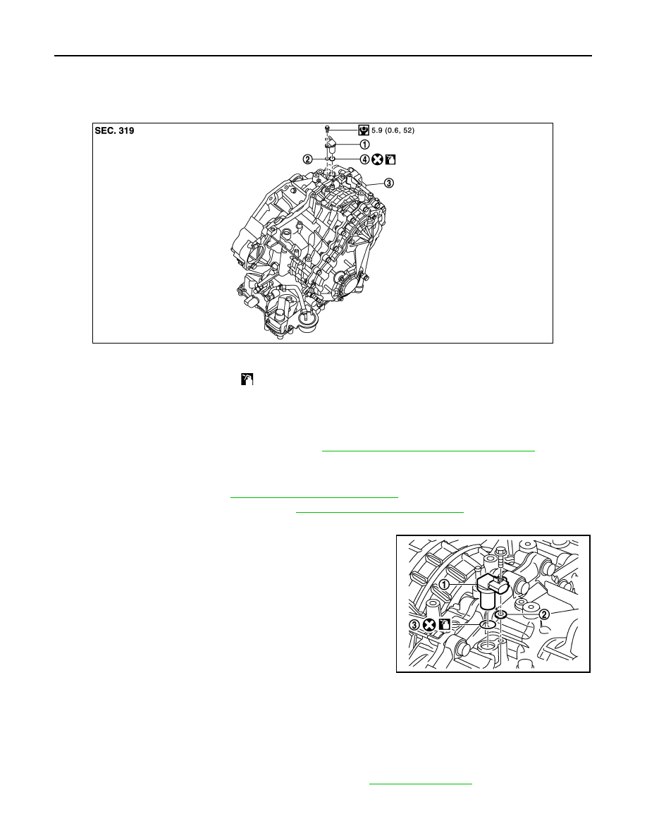
Exploded View
INFOID:0000000010114023
Removal and Installation
INFOID:0000000009469212
REMOVAL
1. Disconnect the battery negative terminal. Refer to
PG-67, "Removal and Installation (Battery)"
2. Remove hoodledge cover (LH).
3. Remove engine room cover.
4. Remove front air duct. Refer to
EM-24, "Removal and Installation"
5. Remove air cleaner case assembly. Refer to
EM-24, "Removal and Installation"
6. Disconnect secondary speed sensor harness connector.
7. Remove secondary speed sensor (1) and shim (2).
CAUTION:
Do not lose the shim.
8. Remove O-ring (3) from secondary speed sensor.
CAUTION:
Do not reuse O-ring.
INSTALLATION
Installation is in the reverse order of removal.
CAUTION:
• Do not reuse O-ring.
• Apply CVT fluid to O-ring.
Inspection
INFOID:0000000010114024
Check for CVT fluid leakage and check CVT fluid level. Refer to
1.
Secondary speed sensor
2.
Shim
3.
Transaxle assembly
4.
O-ring
Apply CVT Fluid NS-2
JPDIA0687GB
JPDIA0617ZZ