Nissan Maxima. Manual - part 1147


  Index      Nissan     Nissan Maxima (2009-2014 year) - Service and Repair Manual


Search            


Content   ..  1145  1146  1147  1148   ..


Nissan Maxima. Manual - part 1147


TM-52

< DTC/CIRCUIT DIAGNOSIS >

[CVT: RE0F09B]

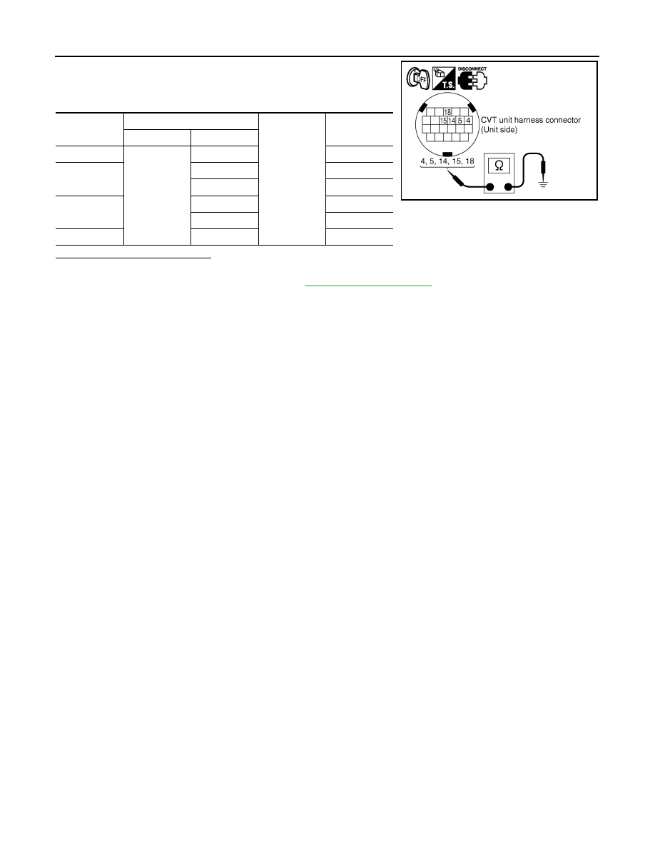
P0705 TRANSMISSION RANGE SWITCH A

Check the continuity of the transmission range switch by changing

selector lever to various positions and checking continuity between

CVT unit terminals and ground.

Is the inspection result normal?

YES

>> INSPECTION END

NO

>> Replace transaxle assembly. Refer to 

TM-188, "Exploded View"

.

Shift position

CVT unit connector

Ground

Continuity

Connector

Terminal

P

F15

4, 5, 14, 15, 18

Not existed

R

4, 15

Existed

5, 14, 18

Not existed

N

4, 5

Existed

14, 15, 18

Not existed

D

4, 5, 14, 15, 18

Existed

SCIA4678E

P0710 TRANSMISSION FLUID TEMPERATURE SENSOR A

TM-53

< DTC/CIRCUIT DIAGNOSIS >

[CVT: RE0F09B]

C

E

F

G

H

I

J

K

L

M

A

B

TM

N

O

P

P0710 TRANSMISSION FLUID TEMPERATURE SENSOR A

Description

INFOID:0000000010113593

The CVT fluid temperature sensor detects the CVT fluid temperature and sends a signal to the TCM.

DTC Logic

INFOID:0000000010113594

DTC DETECTION LOGIC

DTC CONFIRMATION PROCEDURE

CAUTION:

Always drive vehicle at a safe speed.

NOTE:

Immediately after performing any “DTC CONFIRMATION PROCEDURE”, always turn ignition switch OFF.

Then wait at least 10 seconds before performing the next test.

1.

CHECK DTC DETECTION (PART 1)

1. Start the engine.

2. Maintain the following condition for 5 seconds or more.

3. Stop the vehicle.

4. Check the first trip DTC.
Is “P0710” detected?

YES

>> Go to 

TM-54, "Diagnosis Procedure"

.

NO

>> GO TO 2.

2.

CHECK DTC DETECTION (PART 2)

With CONSULT

1. Turn ignition switch OFF and cool the engine.

2. Turn ignition switch ON.

CAUTION:

Never start the engine.

3. Select “Data Monitor” in “TRANSMISSION”.

4. Select “FLUID TEMP”.

5. Record CVT fluid temperature.

6. Start the engine and wait for at least 2 minutes.

7. Drive the vehicle for the total minutes specified in the Driving time column below with the following condi-

tions satisfied.

DTC

Trouble diagnosis name

DTC is detected if...

Possible cause

P0710

Transmission Fluid Tempera-
ture Sensor A Circuit

During running, the CVT fluid temperature 
sensor signal voltage is excessively high or 
low.

• Harness or connectors

(Sensor circuit is open or shorted.)

• CVT fluid temperature sensor

CVT fluid temperature does not rise to 10

°C 

(50

°F) after driving for a certain period of 

time with the TCM-received fluid tempera-
ture sensor value between 

−40°C (−40°F) 

and 9

°C (48.2°F).

The following conditions are maintained for 
5 minutes after the completion of engine di-
agnosis P0111, P0116, and P0196:
• CVT fluid temperature 

− Engine coolant 

temperature > 55

°C (131°F)

• CVT fluid temperature 

− Engine coolant 

temperature < 

−27°C (−16.6°F)

CVT fluid temperature sensor

Vehicle speed

: 20 km/h (12 MPH) or more

Selector lever

: “D” position

TM-54

< DTC/CIRCUIT DIAGNOSIS >

[CVT: RE0F09B]

P0710 TRANSMISSION FLUID TEMPERATURE SENSOR A

8. Stop the vehicle.

9. Check the first trip DTC.

With GST

1. Turn ignition switch OFF and cool the engine.

2. Start the engine and wait for at least 2 minutes.

3. Drive the vehicle and maintain the following conditions for 17 minutes or more.

4. Stop the vehicle.

5. Check the first trip DTC.
Is “P0710” detected?

YES

>> Go to 

TM-54, "Diagnosis Procedure"

.

NO

>> GO TO 3.

3.

CHECK CVT FLUID TEMPERATURE SENSOR

1. Turn ignition switch OFF.

2. Disconnect CVT unit connector.

3. Check resistance between CVT unit connector terminals. 

Is the inspection result normal?

YES

>> INSPECTION END

NO

>> Replace the transaxle assembly due to malfunction in the CVT fluid temperature sensor. Refer to

TM-188, "Exploded View"

.

Diagnosis Procedure

INFOID:0000000010113595

Regarding Wiring Diagram information, refer to 

TM-126, "Wiring Diagram"

.

1.

CHECK CVT FLUID TEMPERATURE SENSOR CIRCUIT

Accelerator pedal position

: 1.0/8 or more

Vehicle speed

: 10 km/h (7 MPH) or more

CVT fluid temperature before engine start

Driving time

−40°C (−40°F) – −31°C (−23.8°F)

17 minutes or more

−30°C (−22°F) – −21°C (−5.8°F)

15 minutes or more

−20°C (−4°F) – −11°C (−12.2°F)

12 minutes or more

−10°C (14°F) – −1°C (30.2°F)

9 minutes or more

0

°C (32°F) – 9°C (48.2°F)

6 minutes or more

10

°C (50°F) or more

(Go to 4.)

Selector lever

: “D” position

Accelerator pedal position

: 1.0/8 or more

Vehicle speed

: 10 km/h (7 MPH) or more

CVT unit

CVT unit

Condition

Resistance

(Approx.)

Connector

Terminal

F46

17

19

When CVT fluid temperature 
is 20

°C (68°F)

6.5 k

When CVT fluid temperature 
is 80

°C (176°F)

0.9 k

AWDIA0098ZZ

P0710 TRANSMISSION FLUID TEMPERATURE SENSOR A

TM-55

< DTC/CIRCUIT DIAGNOSIS >

[CVT: RE0F09B]

C

E

F

G

H

I

J

K

L

M

A

B

TM

N

O

P

1. Turn ignition switch OFF.

2. Disconnect TCM connector.

3. Check resistance between TCM vehicle side harness connector

terminals.

Is the inspection result normal?

YES

>> GO TO 5.

NO

>> GO TO 2.

2.

CHECK HARNESS BETWEEN TCM AND CVT UNIT (CVT TEMPERATURE SENSOR) (PART 1)

1. Disconnect CVT unit connector.

2. Check continuity between TCM vehicle side harness connector

terminals and CVT unit vehicle side harness connector termi-

nals.

Is the inspection result normal?

YES

>> GO TO 3.

NO

>> Repair or replace damaged parts.

3.

CHECK HARNESS BETWEEN TCM AND CVT UNIT (CVT TEMPERATURE SENSOR) (PART 2)

Check continuity between TCM vehicle side harness connector ter-

minals and ground.

Is the inspection result normal?

YES

>> GO TO 4.

NO

>> Repair or replace damaged parts.

4.

CHECK CVT FLUID TEMPERATURE SENSOR

Check CVT fluid temperature sensor. Refer to 

TM-56, "Component Inspection (CVT Fluid Temperature Sen-

sor)"

.

Is the inspection result normal?

YES

>> GO TO 5.

NO

>> Replace transaxle assembly. Refer to 

TM-188, "Exploded View"

.

5.

DETECT MALFUNCTIONING ITEMS

Check TCM connector pin terminals for damage or loose connection with harness connector.
Is the inspection result normal?

YES

>> Replace TCM. Refer to 

TM-168, "Exploded View"

.

NO

>> Repair or replace damaged parts.

TCM vehicle side harness connector

Condition

Resistance 

(Approx.)

Connector

Terminal

F15

13

25

When CVT fluid temperature 
is 20

°C (68°F)

6.5 k

When CVT fluid temperature 
is 80

° (176°F)

0.9 k

AWDIA0095ZZ

TCM vehicle side harness 

connector

CVT unit vehicle side harness 

connector

Continuity

Connector

Terminal

Connector

Terminal

F15 (A)

13

F46 (B)

17

Existed

25

19

AWDIA0096ZZ

TCM vehicle side harness connector

Ground

Continuity

Connector

Terminal

F15

13

Not existed

25

AWDIA0097ZZ


Content   ..  1145  1146  1147  1148   ..