Content .. 1143 1144 1145 1146 ..
Nissan Maxima. Manual - part 1145
TM-44
< DTC/CIRCUIT DIAGNOSIS >
[CVT: RE0F09B]
U1010 CONTROL UNIT (CAN)
U1010 CONTROL UNIT (CAN)
Description
INFOID:0000000010113460
CAN (Controller Area Network) is a serial communication line for real time application. It is an on-vehicle mul-
tiplex communication line with high data communication speed and excellent malfunction detection ability.
Many electronic control units are equipped onto a vehicle, and each control unit shares information and links
with other control units during operation (not independent). In CAN communication, control units are con-
nected with 2 communication lines (CAN-H and CAN-L) allowing a high rate of information transmission with
less wiring. Each control unit transmits/receives data but selectively reads required data only.
DTC Logic
INFOID:0000000010113461
DTC DETECTION LOGIC
DTC CONFIRMATION PROCEDURE
NOTE:
If “DTC CONFIRMATION PROCEDURE” has been previously performed, always turn ignition switch OFF.
Then wait at least 10 seconds before performing the next test.
1.
CHECK DTC DETECTION
With CONSULT
1. Turn ignition switch ON.
2. Start engine and wait for at least 6 seconds.
3. Perform “SELF-DIAG RESULTS” mode for “TRANSMISSION”.
With GST
Follow the procedure “With CONSULT”.
Is “U1010” detected?
YES
>> Go to
NO
>> Check intermittent incident. Refer to
GI-41, "Intermittent Incident"
.
Diagnosis Procedure
INFOID:0000000010113462
1.
CHECK INTERMITTENT INCIDENT
GI-41, "Intermittent Incident"
Is the inspection result normal?
YES
NO
>> Repair or replace damaged parts.
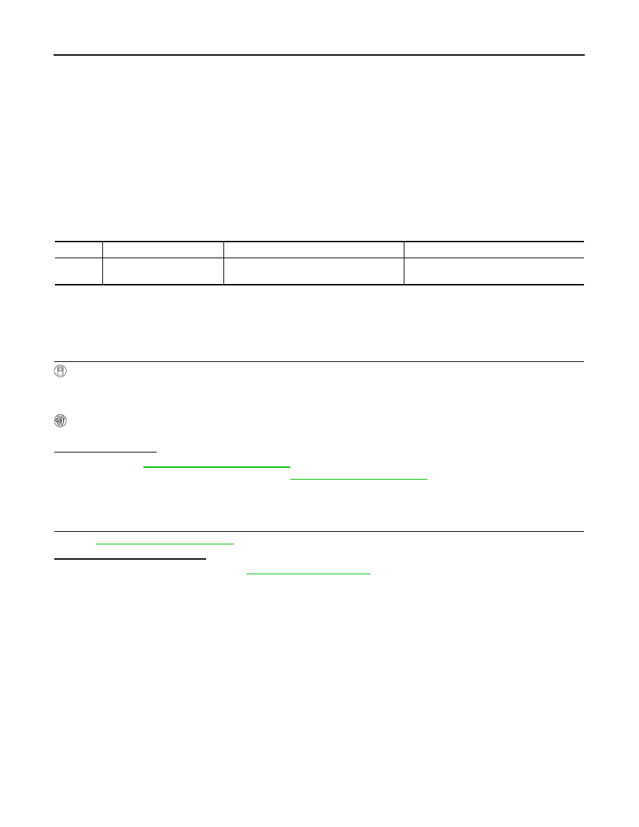
DTC
Trouble diagnosis name
DTC is detected if...
Possible cause
U1010
TCM Communication Mal-
function
When detecting error during the initial diag-
nosis of CAN controller to TCM.
TCM