Nissan Maxima. Manual - part 1146


  Index      Nissan     Nissan Maxima (2009-2014 year) - Service and Repair Manual


Search            


Content   ..  1144  1145  1146  1147   ..


Nissan Maxima. Manual - part 1146


TM-48

< DTC/CIRCUIT DIAGNOSIS >

[CVT: RE0F09B]

P0703 BRAKE SWITCH B

1. Disconnect stop lamp switch connector.

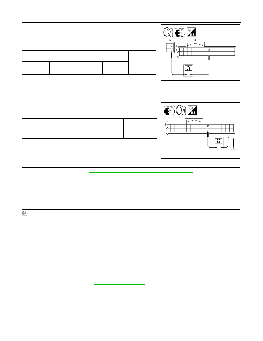
2. Check continuity between stop lamp switch vehicle side harness

connector terminal and BCM vehicle side harness connector ter-

minal.

Is the inspection result normal?

YES

>> GO TO 3.

NO

>> Repair or replace damaged parts.

3.

CHECK HARNESS BETWEEN STOP LAMP SWITCH AND BCM (PART 2)

Check continuity between BCM vehicle side harness connector ter-

minal and ground.

Is the inspection result normal?

YES

>> GO TO 4.

NO

>> Repair or replace damaged parts.

4.

CHECK STOP LAMP SWITCH

Check stop lamp switch. Refer to 

TM-48, "Component Inspection (Stop Lamp Switch)"

.

Is the inspection result normal?

YES

>> Check the following.

• Harness for short or open between battery and stop lamp switch

• 10A fuse [No. 7, located in fuse block (J/B)]

NO

>> Repair or replace stop lamp switch.

5.

CHECK BCM

With CONSULT

1. Turn ignition switch OFF.

2. Connect BCM connector.

3. Turn ignition switch ON.

4. Select “BRAKE SW 1” in “Data Monitor” in “BCM” and verify the proper operation of ON/OFF. Refer to

BCS-41, "Reference Value"

.

Is the inspection result normal?

YES

>> GO TO 6.

NO

>> Replace BCM. Refer to 

BCS-79, "Removal and Installation"

.

6.

DETECT MALFUNCTIONING ITEMS

Check TCM connector pin terminals for damage or loose connection with harness connector.
Is the inspection result normal?

YES

>> Replace TCM. Refer to 

TM-168, "Exploded View"

.

NO

>> Repair or replace damaged parts.

Component Inspection (Stop Lamp Switch)

INFOID:0000000010113469

1.

CHECK STOP LAMP SWITCH

Stop lamp switch vehicle side 

harness connector

BCM vehicle side harness 

connector

Continuity

Connector

Terminal

Connector

Terminal

E38 (A)

4

M18 (B)

26

Existed

AWDIA0599ZZ

BCM vehicle side harness connector

Ground

Continuity

Connector

Terminal

M18

26

Not existed

AWDIA0090ZZ

P0703 BRAKE SWITCH B

TM-49

< DTC/CIRCUIT DIAGNOSIS >

[CVT: RE0F09B]

C

E

F

G

H

I

J

K

L

M

A

B

TM

N

O

P

Check continuity between stop lamp switch connector terminals.

Is the inspection result normal?

YES

>> INSPECTION END

NO

>> Replace stop lamp switch. Refer to 

BR-18, "Exploded View"

.

Stop lamp switch connector

Condition

Continuity

Connector

Terminal

E38

3

 4

Depressed 
brake pedal

Existed

Released 
brake pedal

Not existed

AWDIA0419ZZ

TM-50

< DTC/CIRCUIT DIAGNOSIS >

[CVT: RE0F09B]

P0705 TRANSMISSION RANGE SWITCH A

P0705 TRANSMISSION RANGE SWITCH A

Description

INFOID:0000000010113505

• The Transmission range switch is included in the control valve assembly.

• The Transmission range switch includes 4 transmission position switches.

• TCM judges the selector lever position by the Transmission range switch signal.

DTC Logic

INFOID:0000000010113506

DTC DETECTION LOGIC

DTC CONFIRMATION PROCEDURE

CAUTION:

Always drive vehicle at a safe speed.

NOTE:

Immediately after performing any “DTC CONFIRMATION PROCEDURE”, always turn ignition switch OFF.

Then wait at least 10 seconds before performing the next test.

1.

CHECK DTC DETECTION

With CONSULT

1. Turn ignition switch ON.

2. Select “Data Monitor” in “TRANSMISSION”.

3. Start engine.

4. Drive vehicle and maintain the following conditions for at least 2 consecutive seconds.

With GST

Follow the procedure “With CONSULT”.
Is “P0705” detected?

YES

>> Go to 

TM-50, "Diagnosis Procedure"

.

NO

>> Check intermittent incident. Refer to 

GI-41, "Intermittent Incident"

.

Diagnosis Procedure

INFOID:0000000010113507

Regarding Wiring Diagram information, refer to 

TM-126, "Wiring Diagram"

.

1.

CHECK CVT POSITION

1. Disconnect CVT unit connector.

2. Remove control cable from manual lever. Refer to

TM-173, "Exploded View"

.

3. Check transmission range switch. Refer to 

TM-51, "Component Inspection (Transmisson Range Switch)"

.

Is the inspection result normal?

 Shift position

Transmission range 

switch 1

Transmission range 

switch 2

Transmission range 

switch 3

Transmission range 

switch 4

Transmission range 

switch 3 (monitor)

P

OFF

OFF

OFF

OFF

OFF

R

ON

OFF

OFF

ON

OFF

N

ON

ON

OFF

OFF

OFF

D

ON

ON

ON

ON

ON

DTC

Trouble diagnosis name

DTC is detected if...

Possible cause

P0705

Transmission Range Sensor 
A Circuit (PRNDL Input)

TCM does not receive the correct voltage 
signal (based on the gear position) from the 
switch.

• Harness or connectors

(Transmission range switches circuit is 
open or shorted.)

• Transmission range switch

VEHICLE SPEED

: More than 10 km/h (6 MPH)

ENG SPEED SIG

: More than 450 rpm

ACC PEDAL OPEN

: More than 1.0/8

P0705 TRANSMISSION RANGE SWITCH A

TM-51

< DTC/CIRCUIT DIAGNOSIS >

[CVT: RE0F09B]

C

E

F

G

H

I

J

K

L

M

A

B

TM

N

O

P

YES

>> Adjust CVT position. Refer to 

TM-171, "Inspection and Adjustment"

.

NO

>> GO TO 2.

2.

 CHECK HARNESS BETWEEN TCM AND TRANSMISSION RANGE SWITCH (PART 1)

1. Turn ignition switch OFF.

2. Disconnect TCM connector.

3. Check continuity between TCM vehicle side harness connector

terminals and CVT unit vehicle side harness connector termi-

nals.

Is the inspection result normal?

YES

>> GO TO 3.

NO

>> Repair or replace damaged parts.

3.

 CHECK HARNESS BETWEEN TCM AND TRANSMISSION RANGE SWITCH (PART 2)

Check continuity between TCM vehicle side harness connector ter-

minals and ground.

Is the inspection result normal?

YES

>> GO TO 4.

NO

>> Repair or replace damaged parts.

4.

DETECT MALFUNCTIONING ITEMS

Check TCM connector pin terminals for damage or loose connection with harness connector.
Is the inspection result normal?

YES

>> Replace TCM. Refer to 

TM-168, "Exploded View"

.

NO

>> Repair or replace damaged parts.

Component Inspection (Transmisson Range Switch)

INFOID:0000000010113508

1.

CHECK TRANSMISSION RANGE SWITCH

 TCM vehicle side harness 

connector

 CVT unit vehicle side harness 

connector

Continuity

Connector

Terminal

Connector

Terminal

F15 (A)

1

F46 (B)

5

Existed

2

14

3

15

4

18

11

4

AWDIA0092ZZ

TCM vehicle side harness connector

Ground

Continuity

Connector Terminal

F15

1

Not existed

2

3

4

11

AWDIA0093ZZ


Content   ..  1144  1145  1146  1147   ..