Nissan Maxima. Manual - part 1148


  Index      Nissan     Nissan Maxima (2009-2014 year) - Service and Repair Manual


Search            


Content   ..  1146  1147  1148  1149   ..


Nissan Maxima. Manual - part 1148


TM-56

< DTC/CIRCUIT DIAGNOSIS >

[CVT: RE0F09B]

P0710 TRANSMISSION FLUID TEMPERATURE SENSOR A

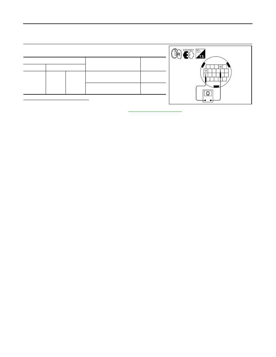
Component Inspection (CVT Fluid Temperature Sensor)

INFOID:0000000010113596

1.

CHECK CVT FLUID TEMPERATURE SENSOR

Check resistance between CVT unit connector terminals.

Is the inspection result normal?

YES

>> INSPECTION END

NO

>> Replace transaxle assembly. Refer to 

TM-188, "Exploded View"

.

CVT unit connector

Condition

Resistance 

(Approx.)

Connector

terminal

F46

17

19

When CVT fluid temperature 
is 20

°C (68°F)

6.5 k

When CVT fluid temperature 
is 80

°C (176°F)

0.9 k

AWDIA0098ZZ

P0715 INPUT SPEED SENSOR A

TM-57

< DTC/CIRCUIT DIAGNOSIS >

[CVT: RE0F09B]

C

E

F

G

H

I

J

K

L

M

A

B

TM

N

O

P

P0715 INPUT SPEED SENSOR A

Description

INFOID:0000000010113600

The primary speed sensor detects the primary pulley revolution speed and sends a signal to the TCM.

DTC Logic

INFOID:0000000010113601

DTC DETECTION LOGIC

DTC CONFIRMATION PROCEDURE

CAUTION:

Always drive vehicle at a safe speed.

NOTE:

Immediately after performing any “DTC CONFIRMATION PROCEDURE”, always turn ignition switch OFF.

Then wait at least 10 seconds before performing the next test.

1.

CHECK DTC DETECTION

With CONSULT

1. Turn ignition switch ON.

2. Select “Data Monitor” in “TRANSMISSION”.

3. Start engine and maintain the following conditions for at least 5 consecutive seconds.

With GST

Follow the procedure “With CONSULT”.
Is “P0715” detected?

YES

>> Go to 

TM-57, "Diagnosis Procedure"

.

NO

>> Check intermittent incident. Refer to 

GI-41, "Intermittent Incident"

.

Diagnosis Procedure

INFOID:0000000010113602

Regarding Wiring Diagram information, refer to 

TM-126, "Wiring Diagram"

.

1.

CHECK PRIMARY SPEED SENSOR

1. Start engine.

2. Check voltage between TCM connector terminals.

DTC

Trouble diagnosis name

DTC is detected if...

Possible cause

P0715

Input/Turbine Speed Sensor 
A Circuit

• Input speed sensor (primary speed sen-

sor) signal is not input due to an open cir-
cuit.

• An unexpected signal is input when vehi-

cle is being driven.

• Harness or connectors

(Sensor circuit is open or shorted.)

• Primary speed sensor

VEHICLE SPEED

: 10 km/h (6 MPH) or more

ACC PEDAL OPEN

: More than 1.0/8

RANGE

: “D” position

ENG SPEED

: 450 rpm or more

Driving location

: Driving the vehicle uphill (increased engine load) will help maintain the driving 
conditions required for this test.

TCM connector

Voltage (Approx.)

Connector

Terminal

F15

25

26

4.75 – 5.25 V

AWDIA0099ZZ

TM-58

< DTC/CIRCUIT DIAGNOSIS >

[CVT: RE0F09B]

P0715 INPUT SPEED SENSOR A

3. If OK, check the pulse when vehicle drive.

Is the inspection result normal?

YES

>> GO TO 7.

NO - 1 >> Battery voltage is not supplied: GO TO 2.

NO - 2 >> Battery voltage is supplied, but there is a malfunction in

the frequency: GO TO 4.

2.

 CHECK HARNESS BETWEEN TCM AND CVT UNIT HARNESS CONNECTOR (SENSOR POWER AND

SENSOR GROUND) (PART 1)
1. Turn ignition switch OFF.

2. Disconnect TCM connector and CVT unit connector.

3. Check continuity between TCM vehicle side harness connector

terminals and CVT unit vehicle side harness connector termi-

nals.

Is the inspection result normal?

YES

>> GO TO 3.

NO

>> Repair or replace damaged parts.

3.

 CHECK HARNESS BETWEEN TCM AND CVT UNIT HARNESS CONNECTOR (SENSOR POWER AND

SENSOR GROUND) (PART 2)
Check continuity between TCM vehicle side harness connector ter-

minals and ground.

Is the inspection result normal?

YES

>> GO TO 6.

NO

>> Repair or replace damaged parts.

4.

 CHECK HARNESS BETWEEN TCM AND CVT UNIT HARNESS CONNECTOR (PRIMARY SPEED SEN-

SOR) (PART 1)

TCM connector

Condition

Voltage 

(Approx.) 

Connector

Terminal

F15

33

When driving [“M

1

”position, 20 km/h (12 

MPH)]

695 Hz

AWDIA0100ZZ

TCM vehicle side harness con-

nector

CVT unit vehicle side harness 

connector

Continuity

Connector

Terminal

Connector

Terminal

F15 (A)

25

F46 (B)

19

Existed

26

20

Existed

AWDIA0101ZZ

TCM vehicle side harness connector 

Ground

Continuity

Connector

Terminal

F15

25

Not existed

26

AWDIA0102ZZ

P0715 INPUT SPEED SENSOR A

TM-59

< DTC/CIRCUIT DIAGNOSIS >

[CVT: RE0F09B]

C

E

F

G

H

I

J

K

L

M

A

B

TM

N

O

P

1. Turn ignition switch OFF.

2. Check continuity between TCM vehicle side harness connector

terminal and CVT unit vehicle side harness connector terminal.

Is the inspection result normal?

YES

>> GO TO 5.

NO

>> Repair or replace damaged parts.

5.

 CHECK HARNESS BETWEEN TCM AND CVT UNIT HARNESS CONNECTOR (PRIMARY SPEED SEN-

SOR) (PART 2)

Check continuity between TCM vehicle side harness connector ter-

minal and ground.

Is the inspection result normal?

YES

>> GO TO 6.

>> Repair or replace damaged parts.

6.

 CHECK THE TCM SHORT

1. Replace with the same type of TCM. Refer to 

TM-168, "Exploded View"

.

2. Connect each connectors.

3. Perform “DTC CONFIRMATION PROCEDURE”. Refer to 

TM-57, "DTC Logic"

.

Is the “P0715” detected again?

YES

>> GO TO 7.

NO

>> Check intermittent incident. Refer to 

GI-41, "Intermittent Incident"

.

7.

DETECT MALFUNCTIONING ITEMS

Check TCM connector pin terminals for damage or loose connection with harness connector.
Is the inspection result normal?

YES

>> Replace TCM. Refer to 

TM-168, "Exploded View"

.

NO

>> Repair or replace damaged parts.

TCM vehicle side harness 

connector 

CVT unit vehicle side harness 

connector

Continuity

Connector

Terminal

Connector

Terminal

F15 (A)

33

F46 (B)

22

Existed

AWDIA0103ZZ

TCM vehicle side harness connector 

Ground

Continuity

Connector

Terminal

F15

33

Not existed

AWDIA0104ZZ


Content   ..  1146  1147  1148  1149   ..