Content .. 1038 1039 1040 1041 ..
Nissan Maxima. Manual - part 1040
FRONT SEAT
SE-133
< UNIT DISASSEMBLY AND ASSEMBLY >
[W/O CLIMATE CONTROLLED SEATS]
C
D
E
F
G
H
I
K
L
M
A
B
SE
N
O
P
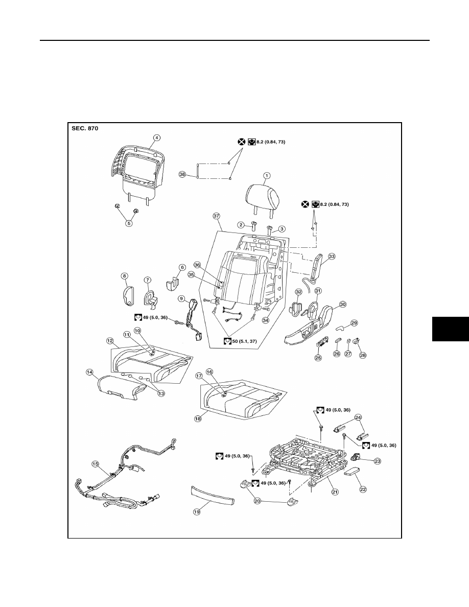
UNIT DISASSEMBLY AND ASSEMBLY
FRONT SEAT
DRIVER SIDE
DRIVER SIDE : Exploded View
INFOID:0000000009468176
Driver Seat - Without Climate Controlled Seats
AWJIA0938ZZ
1.
Headrest
2.
Headrest holder (free)
3.
Headrest holder (locked)
4.
Seatback board
5.
Seatback board clip
6.
Seat cushion inner finisher inside (RH)
7.
Recline mechanism inner cover
8.
Seat cushion outer finisher (RH) 9.
Seat belt buckle