Nissan Altima HL32 Hybrid. Manual - part 657
P0A94-442
HBC-377
< COMPONENT DIAGNOSIS >
D
E
F
G
H
I
J
K
L
M
A
B
HBC
N
O
P
• After disconnecting the service plug grip, wait for at least 10 minutes before touching any of the high-voltage
connectors or terminals.
• Waiting for at least 10 minutes is required to discharge the high-voltage capacitor inside the inverter with
converter assembly.
>> GO TO 2.
2.
CHECK DTC OUTPUT (HYBRID SYSTEM)
1. Turn ignition switch ON.
2. Check DTC.
NOTE:
P0A94-442 may be set due to a malfunction which also causes DTCs in the table above to be set. In this
case, first troubleshoot the output DTCs in the table above.
Then, perform a test to attempt to reproduce the problems, and check that no DTCs are output.
Is DTC detected?
YES
>> Go to Diagnosis Procedure relevant to output DTC.
NO
>> GO TO 3.
3.
CHECK CONNECTOR CONNECTION CONDITION (INVERTER WITH CONVERTER ASSEMBLY CON-
NECTOR)
HBC-109, "Diagnosis Procedure"
OK or NG
OK
>> Replace inverter with converter assembly (See
HBC-638, "Removal and Installation"
).
NG
>> Connect securely.
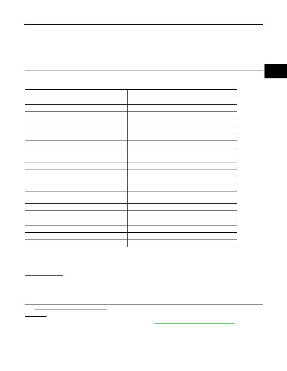
DTC No.
Relevant Diagnosis
P0A1D (Except INF code 390)
Hybrid Powertrain Control Module
P0A1A (all INF codes)
Generator Control Module
P0A1B (all INF codes)
Drive Motor “A” Control Module
P0A72 (all INF codes)
Generator Phase V Current
P0A75 (all INF codes)
Generator Phase W Current
P0A60 (all INF codes)
Drive Motor “A” Phase V Current
P0A63 (all INF codes)
Drive Motor “A” Phase W Current
P0A4B-253
Generator Position Sensor Circuit
P0A4D-255
Generator Position Sensor Circuit Low
P0A4C-513
Generator Position Sensor Circuit Range/Performance
P0A3F-243
Drive Motor “A” Position Sensor Circuit
P0A41-245
Drive Motor “A” Position Sensor Circuit Low
P0A40-500
Drive Motor “A” Position Sensor Circuit Range / Performance
P0A78-266, 267, 306, 510, 523, 586, 505, 287, 506, 503,
279, 504, 806, 807, 808
Drive Motor “A” Inverter Performance
P0A94-585, 587, 589, 590, 554, 555, 556, 547, 548, 549 DC/DC Converter Performance
P0A7A-517, 325, 344, 518, 522, 809, 810, 811
Generator Inverter Performance
P0A92 (all INF codes)
Hybrid Generator Performance
P0A90 (all INF codes)
Hybrid Generator Performance
P0AA6 (all INF codes)
Hybrid Battery Voltage System Isolation Fault
P3000 (all INF codes)
HV Battery Malfunction