Nissan Altima HL32 Hybrid. Manual - part 292


  Index      Nissan     Nissan Altima HL32 Hybrid (2009 year) - Service and Repair Manual


Search            


Content   ..  290  291  292  293   ..


Nissan Altima HL32 Hybrid. Manual - part 292


EC-152

< COMPONENT DIAGNOSIS >

[QR25DE]

P0101 MAF SENSOR

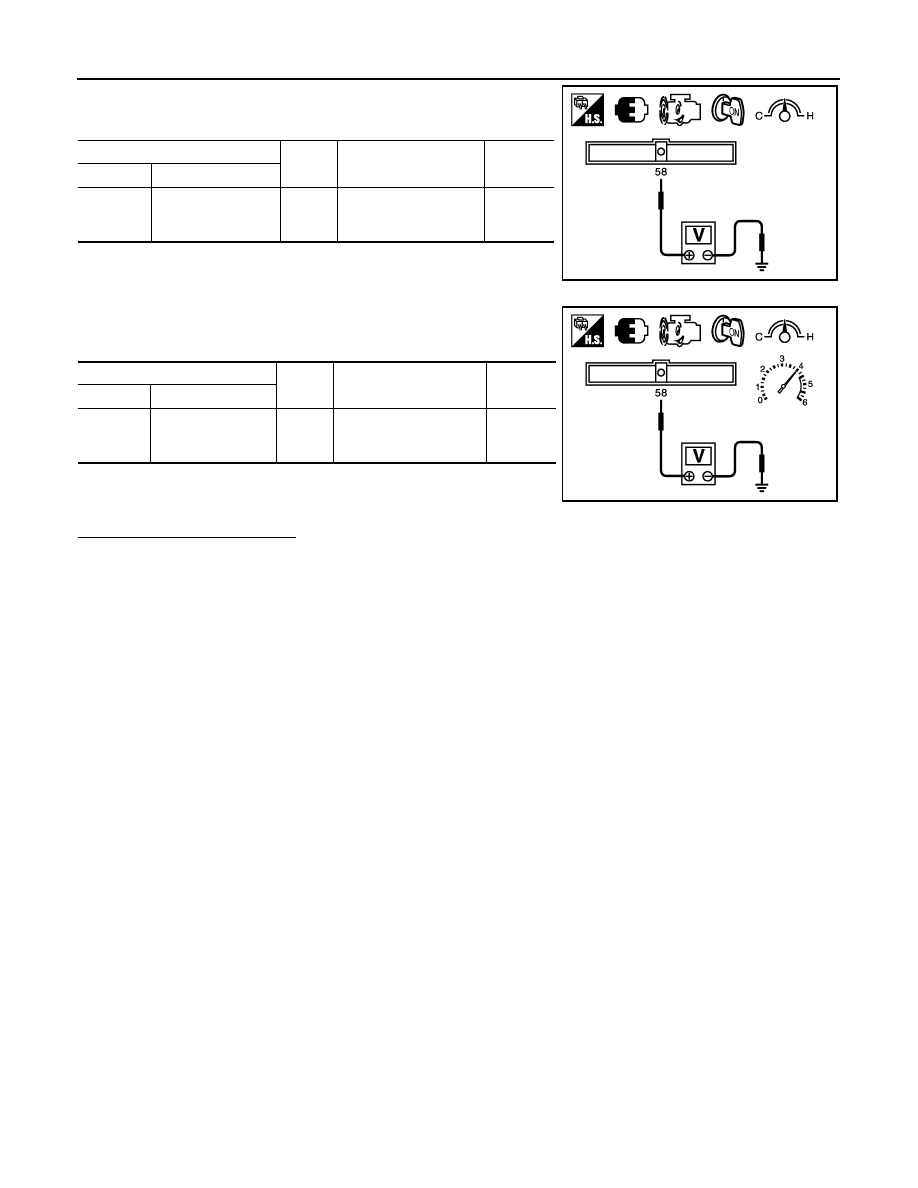
9. Check the voltage between ECM harness connector and

ground.

10. Shift the selector lever to P position.

11. Fully depress the accelerator pedal and keep it.

12. Check the voltage between ECM harness connector and

ground.

13. Fully release accelerator pedal then fully depress it.

14. Check for linear voltage rise in response to engine being

increased to about 2,500 rpm.

Is the inspection result normal?

YES

>> INSPECTION END

NO

>> Clean or replace mass air flow sensor.

ECM

Ground

Condition

Voltage

Connector

Terminal

F13

58

(MAF sensor signal)

Ground

Idle (Engine is warmed-
up to normal operating 
temperature.)

0.9 - 1.2 V

JMBIA1632ZZ

ECM

Ground

Condition

Voltage

Connector

Terminal

F13

58

(MAF sensor signal)

Ground

2,500 rpm (Engine is 
warmed-up to normal op-
erating temperature.)

1.5 - 1.8 V

JMBIA1633ZZ

P0102, P0103 MAF SENSOR

EC-153

< COMPONENT DIAGNOSIS >

[QR25DE]

C

D

E

F

G

H

I

J

K

L

M

A

EC

N

P

O

P0102, P0103 MAF SENSOR

Description

INFOID:0000000004362531

The mass air flow sensor (1) is placed in the stream of intake air. It

measures the intake flow rate by measuring a part of the entire

intake flow. The mass air flow sensor controls the temperature of the

hot wire to a certain amount. The heat generated by the hot wire is

reduced as the intake air flows around it. The more air, the greater

the heat loss. 

Therefore, the electric current supplied to hot wire is changed to

maintain the temperature of the hot wire as air flow increases. The

ECM detects the air flow by means of this current change.

DTC Logic

INFOID:0000000004211390

DTC DETECTION LOGIC

DTC CONFIRMATION PROCEDURE

1.

PRECONDITIONING

If DTC Confirmation Procedure has been previously conducted, always perform the following before conduct-

ing the next test.

1. Turn ignition switch OFF and wait at least 10 seconds.

2. Turn ignition switch ON.

3. Turn ignition switch OFF and wait at least 10 seconds.
Which DTC is detected?

P0102 >> GO TO 2.

P0103 >> GO TO 3.

2.

PERFORM DTC CONFIRMATION PROCEDURE FOR DTC P0102

1. Activate “INSPECTION MODE 1” (

HBC-104

) to start engine, and wait at least 5 seconds.

2. Check DTC.
Is DTC detected?

YES

>> Go to 

EC-154, "Diagnosis Procedure"

.

NO

>> INSPECTION END

3.

PERFORM DTC CONFIRMATION PROCEDURE FOR DTC P0103-I

1. Turn ignition switch ON and wait at least 5 seconds.

2. Check DTC.
Is DTC detected?

YES

>> Go to 

EC-154, "Diagnosis Procedure"

.

NO

>> GO TO 4.

4.

PERFORM DTC CONFIRMATION PROCEDURE FOR DTC P0103-II

1. Activate “INSPECTION MODE 1” (

HBC-104

) to start engine, and wait at least 5 seconds.

2. Check DTC.

PBIA9559J

DTC No.

Trouble diagnosis 

name

DTC detecting condition

Possible cause

P0102

Mass air flow sensor 
circuit low input

An excessively low voltage from the sensor is sent 
to ECM.

• Harness or connectors

(The sensor circuit is open or shorted.)

• Intake air leaks
• Mass air flow sensor

P0103

Mass air flow sensor 
circuit high input

An excessively high voltage from the sensor is 
sent to ECM.

• Harness or connectors

(The sensor circuit is open or shorted.)

• Mass air flow sensor

EC-154

< COMPONENT DIAGNOSIS >

[QR25DE]

P0102, P0103 MAF SENSOR

Is DTC detected?

YES

>> Go to 

EC-154, "Diagnosis Procedure"

.

NO

>> INSPECTION END

Diagnosis Procedure

INFOID:0000000004211391

1.

INSPECTION START

Confirm the detected DTC.
Which DTC is detected?

P0102 >> GO TO 2.

P0103 >> GO TO 3.

2.

CHECK INTAKE SYSTEM

Check the following for connection.

• Air duct

• Vacuum hoses

• Intake air passage between air duct to intake manifold
Is the inspection result normal?

YES

>> GO TO 3.

NO

>> Reconnect the parts.

3.

CHECK GROUND CONNECTION

1. Turn ignition switch OFF.

2. Check ground connection E9. Refer to Ground Inspection in 

GI-45, "Circuit Inspection"

Is the inspection result normal?

YES

>> GO TO 4.

NO

>> Repair or replace ground connection.

4.

CHECK MAF SENSOR POWER SUPPLY CIRCUIT

1. Disconnect mass air flow (MAF) sensor harness connector.

2. Turn ignition switch ON.

3. Check the voltage between MAF sensor harness connector and

ground.

Is the inspection result normal?

YES

>> GO TO 6.

NO

>> GO TO 5.

5.

DETECT MALFUNCTIONING PART

Check the following.

• Junction block connector E44

• Harness for open or short between mass air flow sensor and ECM

• Harness for open or short between mass air flow sensor and IPDM E/R

>> Repair open circuit or short to ground or short to power in harness or connectors.

6.

CHECK MAF SENSOR GROUND CIRCUIT FOR OPEN AND SHORT

1. Turn ignition switch OFF.

2. Disconnect ECM harness connector.

3. Check the continuity between MAF sensor harness connector and ECM harness connector.

MAF sensor

Ground

Voltage

Connector

Terminal

F31

5

Ground

Battery voltage

PBIB1169E

P0102, P0103 MAF SENSOR

EC-155

< COMPONENT DIAGNOSIS >

[QR25DE]

C

D

E

F

G

H

I

J

K

L

M

A

EC

N

P

O

4. Also check harness for short to ground and short to power.
Is the inspection result normal?

YES

>> GO TO 7.

NO

>> Repair open circuit or short to ground or short to power in harness or connectors.

7.

CHECK MAF SENSOR INPUT SIGNAL CIRCUIT FOR OPEN AND SHORT

1. Check the continuity between MAF sensor harness connector and ECM harness connector.

2. Also check harness for short to ground and short to power.
Is the inspection result normal?

YES

>> GO TO 8.

NO

>> Repair open circuit or short to ground or short to power in harness or connectors.

8.

CHECK MASS AIR FLOW SENSOR

Refer to 

EC-155, "Component Inspection"

.

Is the inspection result normal?

YES

>> GO TO 9.

NO

>> Replace mass air flow sensor.

9.

CHECK INTERMITTENT INCIDENT

Refer to 

GI-42, "Intermittent Incident"

.

>> INSPECTION END

Component Inspection

INFOID:0000000004362532

1.

CHECK MASS AIR FLOW SENSOR-I

With CONSULT-III

1. Turn ignition switch OFF.

2. Reconnect all harness connectors disconnected.

3. Lift up the vehicle.

4. Turn ignition switch ON.

5. Connect CONSULT-III and select “DATA MONITOR” mode.

6. Select “MAS A/F SE-B1” and check indication.

7. Activate “INSPECTION MODE 1” (

HBC-104

) to start engine, and warm up engine to normal operating

temperature.

8. Depress the accelerator pedal and keep it.

9. Shift the selector lever to N position with engine running.

CAUTION:

Never leave the selector lever in the N position for a long period of time. In the N position, the

engine operates but electricity cannot be generated.

10. Select “MAS A/F SE-B1” in “DATA MONITOR” and check indication.

MAF sensor

ECM

Continuity

Connector

Terminal

Connector

Terminal

F31

4

F13

56

Existed

MAF sensor

ECM

Continuity

Connector

Terminal

Connector

Terminal

F31

3

F13

58

Existed

Monitor item

Condition

MAS A/F SE-B1

MAS A/F SE-B1

Ignition switch ON

Approx. 0.4 V


Content   ..  290  291  292  293   ..