Nissan Altima HL32 Hybrid. Manual - part 290


  Index      Nissan     Nissan Altima HL32 Hybrid (2009 year) - Service and Repair Manual


Search            


Content   ..  288  289  290  291   ..


Nissan Altima HL32 Hybrid. Manual - part 290


EC-144

< COMPONENT DIAGNOSIS >

[QR25DE]

P0101 MAF SENSOR

P0101 MAF SENSOR

Description

INFOID:0000000004211384

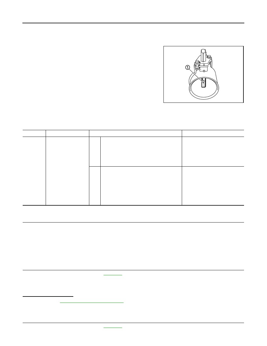
The mass air flow sensor (1) is placed in the stream of intake air. It

measures the intake flow rate by measuring a part of the entire

intake flow. The mass air flow sensor controls the temperature of the

hot wire to a certain amount. The heat generated by the hot wire is

reduced as the intake air flows around it. The more air, the greater

the heat loss. 

Therefore, the electric current supplied to hot wire is changed to

maintain the temperature of the hot wire as air flow increases. The

ECM detects the air flow by means of this current change.

DTC Logic

INFOID:0000000004211385

DTC DETECTION LOGIC

DTC CONFIRMATION PROCEDURE

1.

PRECONDITIONING

If DTC Confirmation Procedure has been previously conducted, always perform the following before conduct-

ing the next test.

1. Turn ignition switch OFF and wait at least 10 seconds.

2. Turn ignition switch ON.

3. Turn ignition switch OFF and wait at least 10 seconds.

>> GO TO 2.

2.

PERFORM DTC CONFIRMATION PROCEDURE FOR MALFUNCTION A

1. Activate “INSPECTION MODE 1” (

HBC-104

) to start engine, and warm up engine to normal operating

temperature.

2. Wait at least 10 seconds at idle speed.

3. Check 1st trip DTC.
Is 1st trip DTC detected?

YES

>> Go to 

EC-146, "Diagnosis Procedure"

.

NO-1 >> With CONSULT-III: GO TO 3.

NO-2 >> With GST: GO TO 5.

3.

CHECK MASS AIR FLOW SENSOR FUNCTION

1. Activate “INSPECTION MODE 1” (

HBC-104

) to start engine, and warm up engine to normal operating

temperature.

PBIA9559J

DTC No.

Trouble diagnosis name

DTC detecting condition

Possible cause

P0101

Mass air flow sensor cir-
cuit range/performance

A)

A high voltage from the sensor is sent to ECM 
under light load driving condition.

• Harness or connectors

(The sensor circuit is open or 
shorted.)

• Mass air flow sensor
• EVAP control system pressure 

sensor

B)

A low voltage from the sensor is sent to ECM un-
der heavy load driving condition.

• Harness or connectors

(The sensor circuit is open or 
shorted.)

• Intake air leaks
• Mass air flow sensor
• EVAP control system pressure 

sensor

• Intake air temperature sensor

P0101 MAF SENSOR

EC-145

< COMPONENT DIAGNOSIS >

[QR25DE]

C

D

E

F

G

H

I

J

K

L

M

A

EC

N

P

O

2. Select “DATA MONITOR” mode with CONSULT-III.

3. Check the voltage of “MAS A/F SE-B1” with “DATA MONITOR”.

4. Increases engine speed to about 2,500 rpm.

5. Monitor the linear voltage rise in response to engine speed

increases.

Is the inspection result normal?

YES

>> GO TO 4.

NO

>> Go to 

EC-146, "Diagnosis Procedure"

.

4.

PERFORM DTC CONFIRMATION PROCEDURE FOR MALFUNCTION B

1. Turn ignition switch OFF.

2. Turn ignition switch ON (READY) and drive vehicle.

3. Maintain the following conditions for at least 10 consecutive seconds.

CAUTION:

Always drive vehicle at a safe speed.

4. Check 1st trip DTC.
Is 1st trip DTC detected?

YES

>> Go to 

EC-146, "Diagnosis Procedure"

.

NO

>> INSPECTION END

5.

PERFORM COMPONENT FUNCTION CHECK FOR MALFUNCTION B

Perform component function check. Refer to 

EC-145, "Component Function Check"

.

NOTE:

Use component function check to check the overall function of the mass air flow sensor circuit. During this

check, a DTC might not be confirmed.
Is the inspection result normal?

YES

>> INSPECTION END

NO

>> Go to 

EC-146, "Diagnosis Procedure"

.

Component Function Check

INFOID:0000000004211386

1.

PERFORM COMPONENT FUNCTION CHECK FOR MALFUNCTION B

With GST

1. Activate “INSPECTION MODE 1” (

HBC-104

) to start engine, and warm up engine to normal operating

temperature.

PBIB3457E

ENG SPEED

More than 1,500 rpm

THRTL SEN 1-B1

More than 1.5V

THRTL SEN 2-B1

More than 1.5V

Shift lever

Suitable position

Driving location

Driving vehicle uphill (Increased engine load) will help 
maintain the driving conditions required for this test.

EC-146

< COMPONENT DIAGNOSIS >

[QR25DE]

P0101 MAF SENSOR

2. Select Service $01 with GST.

3. Check the mass air flow sensor signal with Service $01.

4. Check for linear mass air flow sensor signal value rise in

response to increases to about 2,500 rpm in engine speed.

Is the inspection result normal?

YES

>> INSPECTION END

NO

>> Go to 

EC-146, "Diagnosis Procedure"

.

Diagnosis Procedure

INFOID:0000000004211387

1.

INSPECTION START

Confirm the detected malfunction (A or B). Refer to 

EC-144, "DTC Logic"

.

Which malfunction is detected?

A

>> GO  TO  3.

B

>> GO  TO  2.

2.

CHECK INTAKE SYSTEM

Check the following for connection.

• Air duct

• Vacuum hoses

• Intake air passage between air duct and intake manifold
Is the inspection result normal?

YES

>> GO TO 3.

NO

>> Reconnect the parts.

3.

CHECK GROUND CONNECTION

1. Turn ignition switch OFF.

2. Check ground connection E9. Refer to Ground Inspection in 

GI-45, "Circuit Inspection"

.

Is the inspection result normal?

YES

>> GO TO 4.

NO

>> Repair or replace ground connection.

4.

CHECK MAF SENSOR POWER SUPPLY CIRCUIT

1. Disconnect mass air flow (MAF) sensor harness connector.

2. Turn ignition switch ON.

3. Check the voltage between MAF sensor harness connector and

ground.

Is the inspection result normal?

YES

>> GO TO 6.

NO

>> GO TO 5.

5.

DETECT MALFUNCTIONING PART

Check the following.

• Junction block connector E44

• Harness for open or short between mass air flow sensor and ECM

• Harness for open or short between mass air flow sensor and IPDM E/R

SEF534P

MAF sensor

Ground

Voltage

Connector

Terminal

F31

5

Ground

Battery voltage

PBIB1169E

P0101 MAF SENSOR

EC-147

< COMPONENT DIAGNOSIS >

[QR25DE]

C

D

E

F

G

H

I

J

K

L

M

A

EC

N

P

O

>> Repair open circuit or short to ground or short to power in harness or connectors.

6.

CHECK MAF SENSOR GROUND CIRCUIT FOR OPEN AND SHORT

1. Turn ignition switch OFF.

2. Disconnect ECM harness connector.

3. Check the continuity between MAF sensor harness connector and ECM harness connector.

4. Also check harness for short to ground and short to power.
Is the inspection result normal?

YES

>> GO TO 7.

NO

>> Repair open circuit or short to ground or short to power in harness or connectors.

7.

CHECK MAF SENSOR INPUT SIGNAL CIRCUIT FOR OPEN AND SHORT

1. Check the continuity between MAF sensor harness connector and ECM harness connector.

2. Also check harness for short to ground and short to power.
Is the inspection result normal?

YES

>> GO TO 8.

NO

>> Repair open circuit or short to ground or short to power in harness or connectors.

8.

CHECK INTAKE AIR TEMPERATURE SENSOR

Check intake air temperature sensor.

Refer to 

EC-162, "Component Inspection"

.

Is the inspection result normal?

YES

>> GO TO 9.

NO

>> Replace mass air flow sensor (with intake air temperature sensor).

9.

CHECK EVAP CONTROL SYSTEM PRESSURE SENSOR

Refer to 

EC-286, "Component Inspection"

.

Is the inspection result normal?

YES

>> GO TO 10.

NO

>> Replace EVAP control system pressure sensor.

10.

CHECK MASS AIR FLOW SENSOR

Refer to 

EC-147, "Component Inspection"

.

Is the inspection result normal?

YES

>> GO TO 11.

NO

>> Replace mass air flow sensor.

11.

CHECK INTERMITTENT INCIDENT

Refer to 

GI-42, "Intermittent Incident"

.

>> INSPECTION END

Component Inspection

INFOID:0000000004211388

1.

CHECK MASS AIR FLOW SENSOR-I

With CONSULT-III

MAF sensor

ECM

Continuity

Connector

Terminal

Connector

Terminal

F31

4

F13

56

Existed

MAF sensor

ECM

Continuity

Connector

Terminal

Connector

Terminal

F31

3

F13

58

Existed


Content   ..  288  289  290  291   ..