Nissan Altima HL32 Hybrid. Manual - part 293
EC-156
< COMPONENT DIAGNOSIS >
[QR25DE]
P0102, P0103 MAF SENSOR
11. Shift the selector lever to P position.
12. Fully depress the accelerator pedal and keep it.
13. Check indication.
14. Fully release accelerator pedal then fully depress it.
15. Check for linear voltage rise in response to engine being increased to about 2,500 rpm.
Without CONSULT-III
1. Turn ignition switch OFF.
2. Reconnect all harness connectors disconnected.
3. Lift up the vehicle.
4. Turn ignition switch ON.
5. Check the voltage between ECM harness connector and
ground.
6. Activate “INSPECTION MODE 1” (
) to start engine,
and warm up engine to normal operating temperature.
7. Depress the accelerator pedal and keep it.
8. Shift the selector lever to N position with engine running.
CAUTION:
Never leave the selector lever in the N position for a long period of time. In the N position, the
engine operates but electricity cannot be generated.
9. Check the voltage between ECM harness connector and
ground.
10. Shift the selector lever to P position.
11. Fully depress the accelerator pedal and keep it.
12. Check the voltage between ECM harness connector and
ground.
13. Fully release accelerator pedal then fully depress it.
14. Check for linear voltage rise in response to engine being
increased to about 2,500 rpm.
Monitor item
Condition
MAS A/F SE-B1
MAS A/F SE-B1
Idle (Engine is warmed-up to normal operat-
ing temperature.)
0.9 - 1.2 V
Monitor item
Condition
MAS A/F SE-B1
MAS A/F SE-B1
2,500 rpm (Engine is warmed-up to normal
operating temperature.)
1.5 - 1.8 V
ECM
Ground
Condition
Voltage
Connector
Terminal
F13
58
(MAF sensor signal)
Ground Ignition switch ON
Approx. 0.4 V
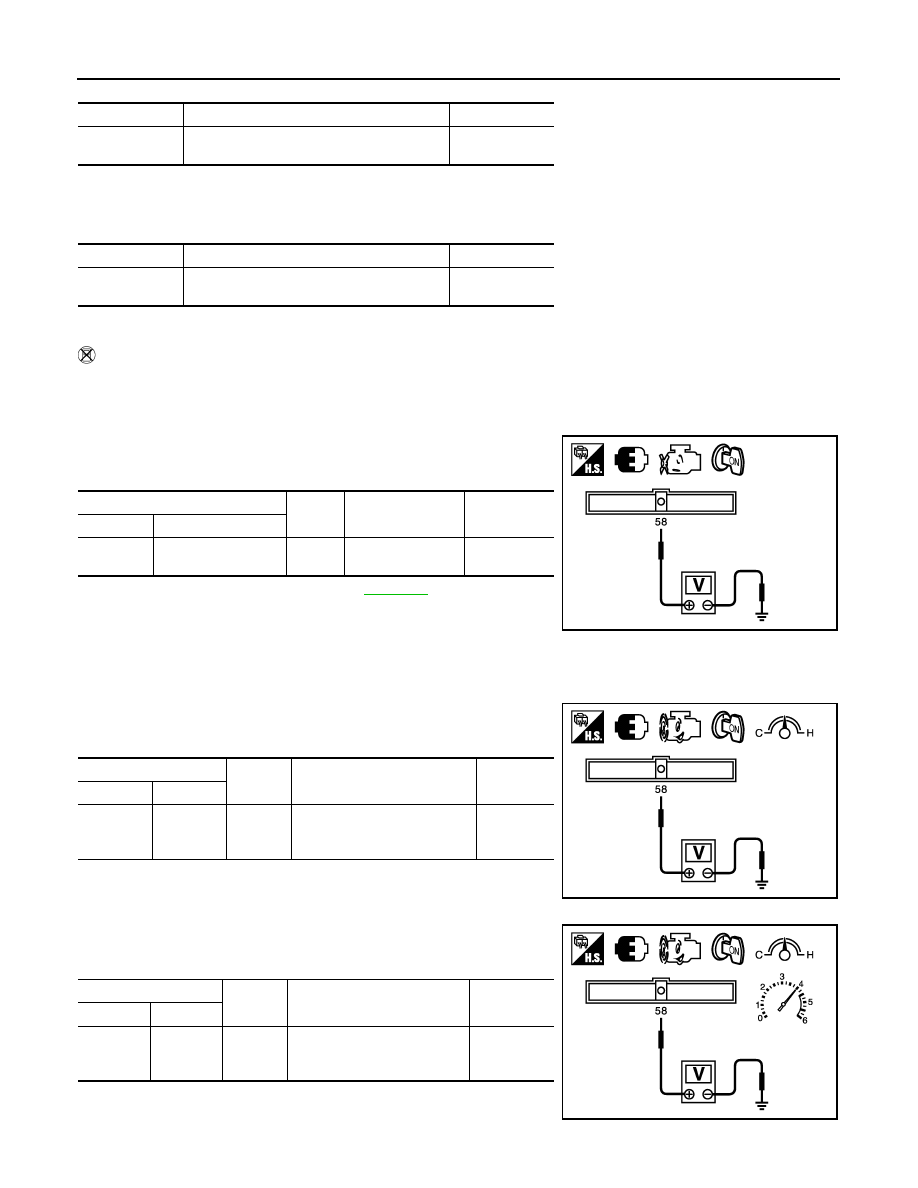
ECM
Ground
Condition
Voltage
Connector
Terminal
F13
58
(MAF sen-
sor signal)
Ground
Idle (Engine is warmed-up to
normal operating tempera-
ture.)
0.9 - 1.2 V
JMBIA1631ZZ
JMBIA1632ZZ
ECM
Ground
Condition
Voltage
Connector
Terminal
F13
58
(MAF sen-
sor signal)
Ground
2,500 rpm (Engine is warmed-
up to normal operating tem-
perature.)
1.5 - 1.8 V
JMBIA1633ZZ