Nissan Frontier. Manual - part 721


  Index      Nissan     Nissan Frontier (2014 year) - Service and Repair Manual


Search            


Content   ..  719  720  721  722   ..


Nissan Frontier. Manual - part 721


CYLINDER HEAD

EM-73

< REMOVAL AND INSTALLATION >

[QR25DE]

C

D

E

F

G

H

I

J

K

L

M

A

EM

N

P

O

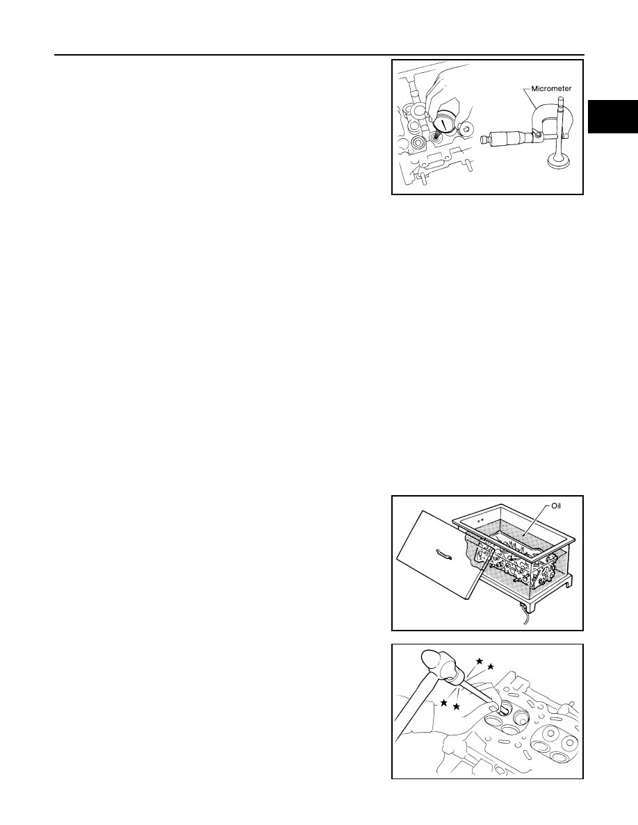
Measure the diameter of valve stem with micrometer.

Valve Guide Inner Diameter

Measure the inner diameter of valve guide with inside micrometer.

Valve Guide Clearance

(Valve guide clearance) = (Valve guide inner diameter) – (Valve stem diameter).

• If it exceeds the limit, replace valve guide and/or valve.

VALVE GUIDE REPLACEMENT

When valve guide is removed, replace with oversized [0.2 mm (0.008 in)] valve guide.
1. To remove valve guide, heat cylinder head to 110

° to 130°C

(230

° to 266°F) by soaking in heated oil.

2. Drive out valve guide with a press [under a 20 kN (2 ton, 2.2 US

ton, 2.0 lmp ton) force] or suitable tool.

WARNING:

Cylinder head contains heat, when working, wear protective

equipment to avoid getting burned.

Standard

Intake

: 5.965 - 5.980 mm (0.2348 - 0.2354 in)

Exhaust

: 5.955 - 5.970 mm (0.2344 - 0.2350 in)

SEM938C

Standard

Intake and Exhaust

: 6.000 - 6.018 mm (0.2362 - 0.2369 in)

Valve guide clearance:
Standard

Intake

: 0.020 - 0.053 mm (0.0008 - 0.0021 in)

Exhaust : 0.030 - 0.063 mm (0.0012 - 0.0025 in)

Limit

Intake

: 0.08 mm (0.003 in)

Exhaust : 0.09 mm (0.004 in)

SEM008A

SEM931C

EM-74

< REMOVAL AND INSTALLATION >

[QR25DE]

CYLINDER HEAD

3. Ream cylinder head valve guide hole using suitable tool.

4. Heat cylinder head to 110

° to 130°C (230° to 266°F) by soaking

in heated oil.

5. Press valve guide from camshaft side to the dimensions as

shown using suitable tool.

WARNING:

Cylinder head contains heat, when working, wear protective

equipment to avoid getting burned.

6. Apply reamer finish to valve guide using suitable tool.

VALVE SEAT CONTACT

Valve guide hole diameter (for service parts):

Intake and exhaust

: 10.175 - 10.196 mm (0.4006 - 0.4014 in)

SEM932C

SEM008A

Projection (H)

Intake

: 10.1 - 10.3 mm (0.398 - 0.406 in)

Exhaust

: 10.0 - 10.4 mm (0.394 - 0.409 in)

PBIC2187E

Standard

Intake and exhaust:

6.000 - 6.018 mm (0.2362 - 0.2369 in)

SEM932C

CYLINDER HEAD

EM-75

< REMOVAL AND INSTALLATION >

[QR25DE]

C

D

E

F

G

H

I

J

K

L

M

A

EM

N

P

O

• After confirming that the dimensions of valve guides and valves are

within specifications, perform this procedure. 

• Apply prussian blue (or white lead) onto contacting surface of valve

seat to check the condition of the valve contact on the surface.

• Check if the contact area band is continuous all around the circum-

ference.

• If not, grind to adjust valve fitting and check again. If the contacting

surface still has NG conditions even after the re-check, replace

valve seat.

VALVE SEAT REPLACEMENT

When valve seat is removed, replace with oversized [0.5 mm (0.020 in)] valve seat.
1. Bore out old seat until it collapses. Boring should not continue beyond the bottom face of the seat recess

in cylinder head. Set the machine depth stop to ensure this. Refer to 

EM-108, "Standard and Limit"

.

CAUTION:

Prevent scratching cylinder head by excessive boring.

2. Ream cylinder head recess diameter for service valve seat.

• Be sure to ream in circles concentric to the valve guide center.

This will enable valve seat to fit correctly.

3. Heat cylinder head to 110

° to 130°C (230° to 266°F) by soaking

in heated oil.

4. Provide valve seats cooled well with dry ice. Force fit valve seats into cylinder head.

WARNING:

• Cylinder head contains heat. When working, wear protective equipment to avoid getting burned.

CAUTION:

• Avoid directly touching cold valve seats.

5. Finish seat to the specified dimensions using suitable tool. Refer

to 

EM-108, "Standard and Limit"

.

CAUTION:

When using valve seat cutter, firmly grip cutter handle with

both hands. Then, press on the contacting surface all

around the circumference to cut in a single drive. Improper

pressure on the cutter or cutting many different times may

result in staged valve seat. 

SBIA0322E

Oversize [0.5 mm (0.020 in)]

Intake

: 37.000 - 37.016 mm (1.4567 - 1.4573 in)

Exhaust

: 32.000 - 32.016 mm (1.2598 - 1.2605 in)

SEM795A

SEM008A

SEM934C

EM-76

< REMOVAL AND INSTALLATION >

[QR25DE]

CYLINDER HEAD

6. Using compound, grind to adjust valve fitting. 
7. Check again for normal contact.

VALVE SPRING SQUARENESS

• Set a try square along the side of valve spring and rotate spring.

Measure the maximum clearance between the top face of spring

and try square.

CAUTION:

Do not remove valve spring seat from valve spring.

• If it exceeds the limit, replace valve spring.

VALVE SPRING DIMENSIONS AND VALVE SPRING PRESSURE LOAD

• Check valve spring pressure with valve spring seat installed at the

specified spring height. Refer to 

EM-108, "Standard and Limit"

.

CAUTION:

Do not remove valve spring seat from valve spring.

• If the installation load or load with valve open is out of the stan-

dard, replace valve spring.

Limit
Intake

: 1.8 mm (0.071 in)

Exhaust

: 1.9 mm (0.075 in)

PBIC0080E

SEM113


Content   ..  719  720  721  722   ..