Nissan Frontier. Manual - part 722
ENGINE ASSEMBLY
EM-77
< UNIT REMOVAL AND INSTALLATION >
[QR25DE]
C
D
E
F
G
H
I
J
K
L
M
A
EM
N
P
O
UNIT REMOVAL AND INSTALLATION
ENGINE ASSEMBLY
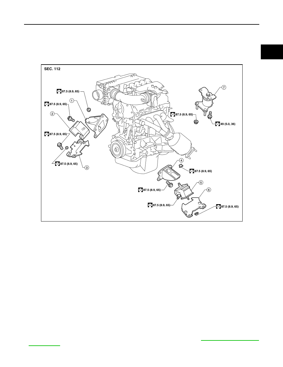
Exploded View
INFOID:0000000009478076
Removal and Installation
INFOID:0000000009478077
WARNING:
• Situate vehicle on a flat and solid surface.
• Place chocks at front and back of rear wheels.
• For engines not equipped with engine slingers, attach proper slingers and bolts described in PARTS
CATALOG.
CAUTION:
• Always be careful to work safely, avoid forceful or uninstructed operations.
• Do not start working until exhaust system and engine coolant are cooled sufficiently.
• If items or work required are not covered by the engine section, follow the procedures in the applica-
ble procedures.
• Always use the support point specified for lifting.
• Use either 2-pole lift type or separate type lift. If board-on type is used for unavoidable reasons, sup-
port at the rear axle jacking point with transmission jack or similar tool before starting work, in prep-
aration for the backward shift of center of gravity.
• For supporting points for lifting and jacking point at rear axle. Refer to
NOTE:
1. RH engine mounting bracket (upper)
2. RH engine mounting insulator
3. RH engine mounting bracket (lower)
4. LH engine mounting bracket (upper)
5. LH engine mounting insulator
6. LH engine mounting bracket (lower)
7. Rear engine mounting insulator
AWBIA0869GB