Nissan Frontier. Manual - part 720


  Index      Nissan     Nissan Frontier (2014 year) - Service and Repair Manual


Search            


Content   ..  718  719  720  721   ..


Nissan Frontier. Manual - part 720


CYLINDER HEAD

EM-69

< REMOVAL AND INSTALLATION >

[QR25DE]

C

D

E

F

G

H

I

J

K

L

M

A

EM

N

P

O

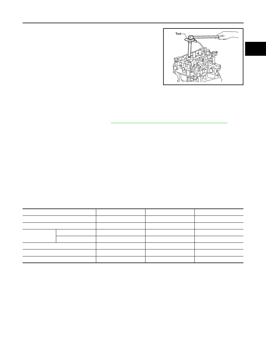
• Measure the tightening angle using Tool.

3. Installation of the remaining parts is in reverse order of removal. 

INSPECTION AFTER INSTALLATION

• Before starting engine, check oil/fluid levels including engine coolant and engine oil. If less than required

quantity, fill to the specified level. Refer to 

MA-16, "FOR USA AND CANADA : Fluids and Lubricants"

 (United

States and Canada).

• Use procedure below to check for fuel leakage.

• Turn ignition switch ON (with engine stopped). With fuel pressure applied to fuel piping, check for fuel leak-

age at connection points.

• Start engine. With engine speed increased, check again for fuel leakage at connection points.

• Run engine to check for unusual noise and vibration.

NOTE:

If hydraulic pressure inside timing chain tensioner drops after removal and installation, slack in the guide

may generate a pounding noise during and just after engine start. However, this is normal. Noise will stop

after hydraulic pressure rises.

• Warm up engine thoroughly to make sure there is no leakage of fuel, exhaust gas, or any oils/fluids including

engine oil and engine coolant.

• Bleed air from passages in lines and hoses, such as in cooling system.

• After cooling down engine, again check oil/fluid levels including engine oil and engine coolant. Refill to spec-

ified level, if necessary.

• Summary of the inspection items:

*Power steering fluid, brake fluid, etc.

Tool number

: KV10112100 (BT-8653-A)

Step a

: 55.0 N·m (5.6 kg-m, 41 ft-lb) 

Step b

: Loosen to 0 N·m in the reverse order of 
tightening.

Step c

: 39.2 N·m (4.0 kg-m, 29 ft-lb)

Step d

: 75

° clockwise

Step e

: 75

° clockwise

WBIA0617E

Item

Before starting engine

Engine running

After engine stopped

Engine coolant

Level

Leakage

Level

Engine oil

Level

Leakage

Level

Transmission/
transaxle fluid 

A/T and CVT Models

Leakage

Level/Leakage

Leakage

M/T Models

Level/Leakage

Leakage

Level/Leakage

Other oils and fluids*

Level

Leakage

Level

Fuel

Leakage

Leakage

Leakage

Exhaust gas

Leakage

EM-70

< REMOVAL AND INSTALLATION >

[QR25DE]

CYLINDER HEAD

Exploded View

INFOID:0000000009478073

Disassembly and Assembly

INFOID:0000000009478074

DISASSEMBLY

1. Remove spark plug.
2. Remove valve lifter.

• Identify installation positions, and store them without mixing them up.

3. Remove valve collet, valve spring retainer and valve spring

using Tool. 

CAUTION:

• When working, be careful not to damage valve lifter holes.

• Do not remove valve spring seat from valve spring.

4. Push valve stem to combustion chamber side, and remove valve. 

• Identify installation positions, and store them without mixing them up.

1.

Valve collet

2.

Valve spring retainer

3.

Valve spring (with valve spring seat)

4.

Valve oil seal

5.

Valve guide

6.

Cylinder head

7.

Valve seat

8.

Valve (INT)

9.

Valve (EXH)

10. Spark plug tube

11. Spark plug

PBIC3024E

Tool numbers

: KV10116200 (J-26336-A)
: KV10115900 (J-26336-20)
: KV10109220 ( — )

WBIA0477E

CYLINDER HEAD

EM-71

< REMOVAL AND INSTALLATION >

[QR25DE]

C

D

E

F

G

H

I

J

K

L

M

A

EM

N

P

O

5. Remove valve oil seal using Tool.

6. When valve seat must be replaced. Refer to 

EM-72, "Inspection After Disassembly"

.

7. When valve guide must be replaced. Refer to 

EM-72, "Inspection After Disassembly"

.

8. Remove spark plug tube, if necessary.

• Remove it from cylinder head using suitable tool.

CAUTION:

• Be careful not to damage cylinder head.

• Once removed, spark plug tube will be deformed and cannot be reused. Do not remove it

unless absolutely necessary.

ASSEMBLY

1. Install valve guide if removed. Refer to 

EM-72, "Inspection After Disassembly"

.

2. Install valve seat if removed. Refer to 

EM-72, "Inspection After Disassembly"

.

3. Install valve oil seal using Tool.

NOTE:

Install with the valve oil seal to match dimension as shown.

4. Install valve.

NOTE:

Install larger diameter to intake side.

5. Install valve spring (with valve spring seat).

NOTE:

• Install smaller pitch (valve spring seat side) to cylinder head

side.

• Confirm identification color of valve spring.

6. Install valve spring retainer.
7. Install valve collet using Tool.

Tool numbers

: KV10115600 (J-38958)

WBIA0478E

Tool numbers

: KV10115600 (J-38958)

Height (H)

: 11.8 - 12.4 mm (0.465 - 0.488 in)

WBIA0653E

Intake

: Blue

Exhaust

: Yellow

PBIC0525E

Tool numbers

: KV10116200 (J-26336-A)
: KV10115900 (J-26336-20)
: KV10109220 ( — )

EM-72

< REMOVAL AND INSTALLATION >

[QR25DE]

CYLINDER HEAD

• Install valve collet with a magnet hand.

CAUTION:

When working, be careful not to damage valve lifter holes.

• Tap valve stem edge lightly with a plastic hammer after instal-

lation to check its installed condition.

8. Install valve lifter.

• Install it in the original position.

9. Install spark plug tube if removed.

• Press-fit it into cylinder head as follows:

a. Remove old sealant from cylinder head side installation hole.
b. Apply sealant within approximately 12 mm (0.47 in) from edge of

spark plug tube press-fit side.

Use Genuine High Strength Locking Sealant or equivalent.

Refer to 

GI-21, "Recommended Chemical Products and

Sealants"

.

c.

Press-fit spark plug tube so that its height (H) is as specified

using suitable tool.

CAUTION:

• When press-fitting, be careful not to deform spark plug tube.

• After press-fitting, wipe off any protruding sealant on top surface of cylinder head.

10. Install spark plug.

Inspection After Disassembly

INFOID:0000000009478075

VALVE DIMENSIONS

• Check dimensions of each valve. Refer to 

EM-108, "Standard and

Limit"

.

• If dimensions are out of the standard, replace valve and check the

valve seat contact.

VALVE GUIDE CLEARANCE

Valve Stem Diameter

WBIA0578E

Standard press-fit 
height (H)

: 41.2 - 42.2 mm (1.622 - 1.661 in)

PBIC2713E

SEM188A


Content   ..  718  719  720  721   ..