Nissan Frontier. Manual - part 719


  Index      Nissan     Nissan Frontier (2014 year) - Service and Repair Manual


Search            


Content   ..  717  718  719  720   ..


Nissan Frontier. Manual - part 719


OIL SEAL

EM-65

< REMOVAL AND INSTALLATION >

[QR25DE]

C

D

E

F

G

H

I

J

K

L

M

A

EM

N

P

O

• Press-fit front oil seal until it is flush with front end surface of

front cover using suitable tool.

CAUTION:

• Be careful not to damage front cover and crankshaft.

• Press-fit straight and avoid causing burrs or tilting oil

seal.

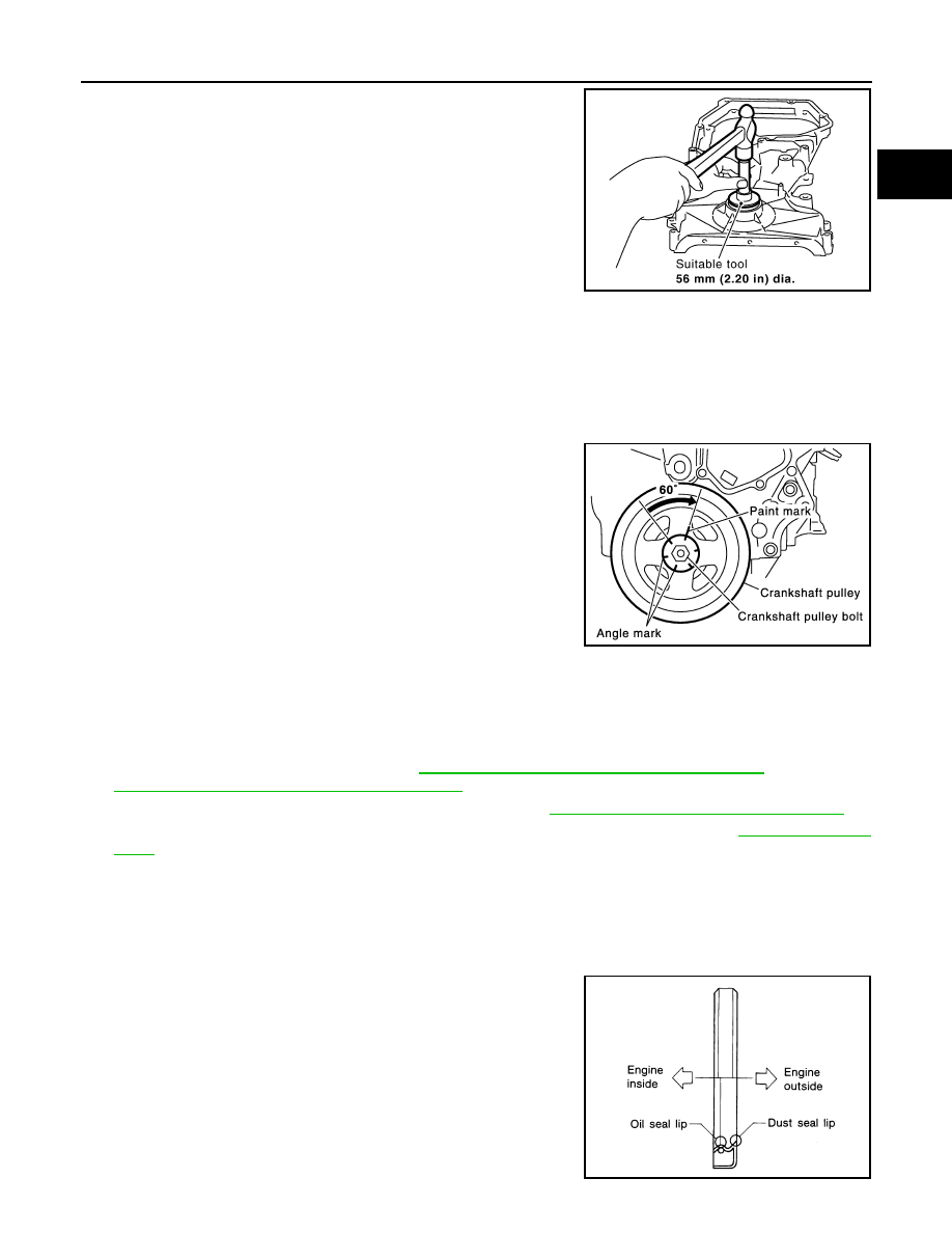
3. Tighten crankshaft pulley bolt.

• Secure crankshaft pulley using suitable tool, and tighten crankshaft pulley bolt.

a. Apply new engine oil to thread and seat surfaces of crankshaft pulley bolt.
b. Tighten crankshaft pulley bolt.

c. Put a paint mark on crankshaft pulley, mating with any one of six

easy to recognize angle marks on bolt flange. 

d. Turn another 60

° degrees clockwise (angle tightening).

• Check the tightening angle with movement of one angle mark.

4. Installation is in the reverse order of removal after this step.

Removal and Installation of Rear Oil Seal

INFOID:0000000009478070

REMOVAL

1. Remove transmission assembly. Refer to 

TM-21, "Removal and Installation from Vehicle"

 (M/T models),

TM-306, "Removal and Installation for QR25DE"

 (A/T models).

2. Remove clutch cover and clutch disk (M/T models). Refer to 

CL-19, "5M/T : Removal and Installation"

3. Remove drive plate (A/T models) or flywheel (M/T models) with power tool. Refer to 

EM-80, "Exploded

View"

.

4. Remove rear oil seal with a suitable tool.

CAUTION:

Be careful not to damage crankshaft and cylinder block.

INSTALLATION

1. Apply new engine oil to new rear oil seal joint surface and seal lip.
2. Install rear oil seal so that each seal lip is oriented as shown.

PBIC3033E

Crankshaft pulley bolt

: 42.1 N·m (4.3 kg-m, 31 ft-lb)

SEM751G

SEM715A

EM-66

< REMOVAL AND INSTALLATION >

[QR25DE]

OIL SEAL

• Install new rear oil seal using suitable tool. [outside diameter

102 mm (4.02 in), inside diameter 86 mm (3.39 in)].

CAUTION:

• Be careful not to damage crankshaft and cylinder block.

• Press-fit oil seal straight to avoid causing burrs or tilt-

ing.

• Do not touch grease applied onto oil seal lip.

• Press in rear oil seal to the position as shown.

3. Installation of the remaining components is in the reverse order of removal.

CAUTION:

• When replacing an engine or transmission you must make sure the dowels are installed cor-

rectly during reassembly.

• Improper alignment caused by missing dowels may cause vibration, oil leaks or breakage of

drivetrain components.

SBIA0280E

WBIA0654E

CYLINDER HEAD

EM-67

< REMOVAL AND INSTALLATION >

[QR25DE]

C

D

E

F

G

H

I

J

K

L

M

A

EM

N

P

O

CYLINDER HEAD

Exploded View

INFOID:0000000009478071

Removal and Installation

INFOID:0000000009478072

NOTE:

When removing components such as hoses, tubes/lines, etc., cap or plug openings to prevent fluid from spill-

ing.

REMOVAL

1. Release fuel pressure. Refer to 

EC-466, "Fuel Pressure Check"

.

2. Drain engine coolant. Refer to 

CO-12, "Changing Engine Coolant"

.

CAUTION:

• Perform this step when the engine is cold.

• Do not spill engine coolant on drive belt.

3. Drain engine oil. Refer to 

LU-10, "Changing Engine Oil"

.

CAUTION:

• Perform this step when the engine is cold.

• Do not spill engine oil on drive belt.

4. Remove intake manifold. Refer to 

EM-27

.

5. Remove fuel injector and fuel tube assembly. Refer to 

EM-39

.

6. Remove exhaust manifold and three way catalyst assembly. Refer to 

EM-31

.

7. Remove water outlet. Refer to 

CO-28, "Removal and Installation"

.

8. Remove heater outlet. Refer to 

CO-28, "Exploded View"

.

NOTE:

Can be removed and installed even when assembled with cylinder head.

9. Remove front cover and timing chain. Refer to 

EM-46

.

10. Remove camshafts. Refer to 

EM-54

.

1.

Cylinder head assembly

2.

Cylinder head gasket

3.

Cylinder head bolt

A. Refer to 

EM-67, "Removal and Installation"

WBIA0835E

EM-68

< REMOVAL AND INSTALLATION >

[QR25DE]

CYLINDER HEAD

11. Loosen cylinder head bolts in reverse order as shown using

power tool. 

12. Remove cylinder head.
13. Remove cylinder head gasket.

INSPECTION AFTER REMOVAL

Cylinder Head Bolts Outer Diameter

• Cylinder head bolts are tightened by plastic zone tightening

method. Whenever the size difference between (d1) and (d2)

exceeds the limit, replace them with a new one. 

• If reduction of outer diameter appears in a position other than (d2),

use it as (d2) point.

Cylinder Head Distortion

NOTE:

When performing this inspection, cylinder block distortion should also be checked. Refer to 

EM-91, "Inspection

After Disassembly"

.

1. Using suitable tool, wipe off oil, scale, gasket, sealant and carbon deposits from surface of cylinder head.

CAUTION:

Do not allow gasket fragments to enter engine oil or engine coolant passages.

2. At each of several locations on bottom surface of cylinder head,

measure the distortion in six directions.

• If it exceeds the limit, replace cylinder head.

INSTALLATION

1. Install new cylinder head gasket.
2. Install cylinder head following the steps below to tighten cylinder

head bolts in numerical order as shown.

CAUTION:

If cylinder head bolts re-used, check their outer diameters

before installation. Follow the "Cylinder Head Bolts Outer

Diameter" procedure.

NOTE:

Apply new engine oil to threads and seating surfaces of bolts.

KBIA0058E

Limit [(d1) (d2)]: 0.23 mm (0.0091 in)

WBIA0836E

Limit

: 0.1 mm (0.004 in)

PBIC0075E

KBIA0058E


Content   ..  717  718  719  720   ..