Nissan Sentra. Manual - part 907
TM-264
< REMOVAL AND INSTALLATION >
[CVT: RE0F11A]
AIR BREATHER HOSE
AIR BREATHER HOSE
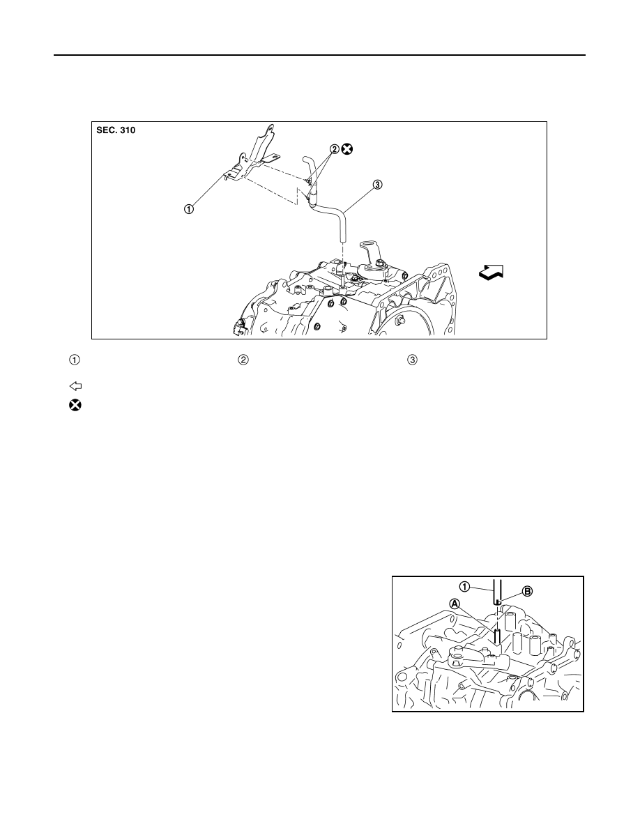
Exploded View
INFOID:0000000009759511
Removal and Installation
INFOID:0000000009759512
REMOVAL
1. Remove clips from harness bracket.
2. Remove air breather hose from transaxle assembly.
INSTALLATION
Installation is in the reverse order of removal.
CAUTION:
• Do not bend the air breather hose to prevent damage to the hose.
• Do not reuse clips.
• Securely install the clips to the harness bracket.
• Be sure to insert it fully until its end reaches the stop when
inserting air breather hose (1) to transaxle tube (A).
• Install air breather hose to transaxle tube so that the paint
mark (B) is facing frontward.
Harness bracket
.
Clip
.
Air breather hose
: Vehicle front
: Always replace after every disassembly.
JSDIA3584ZZ
JSDIA1887ZZ